Thanks for the support as always dude!
Send me a DM regarding Raiden Fighters with a few photographs and we can figure something out!
1 Like
Nintendo DS Lite Cartridge Slot repairs:
I’ve done a lot of DS Lite repairs and generally they have never really been worth the time or effort to work on considering how cheap they can still currently be obtained for, the many issues they can end up having and the comparatively high cost of replacement parts.
However, recently I got handed over two very nice condition DS lites:

Everything is working great apart from both of them have non working “SLOT 1” DS cartridge slots.
The deal here being if I can repair them I get to keep the black DS lite for myself.
Which I decided to take up as the only DS lite I had is actually the result of combining many trash free systems together to make one working system and even then I still had to use parts of a 3rd party shell casing to bring it all together.
So anyway, I bought 2 replacement DS cartridge slots from Zedlabs:

Turning over the Pink DS lite and removing the Dummy GBA Cartridge:

The Battery and two feet are removed:
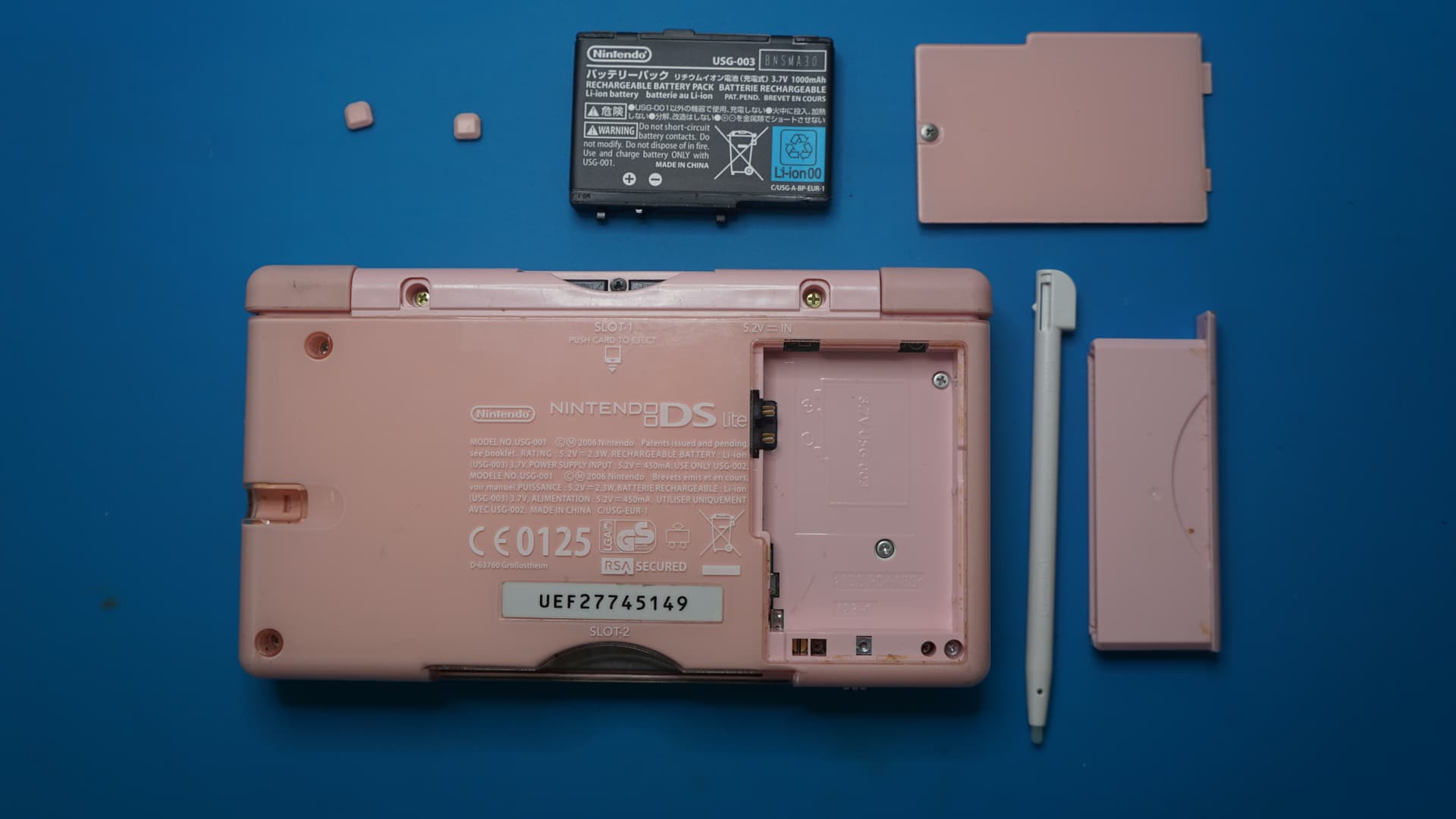
Four Tri-wing screws and three Phillips screws have to be removed:

You can leave the screw in the center of the battery housing alone:

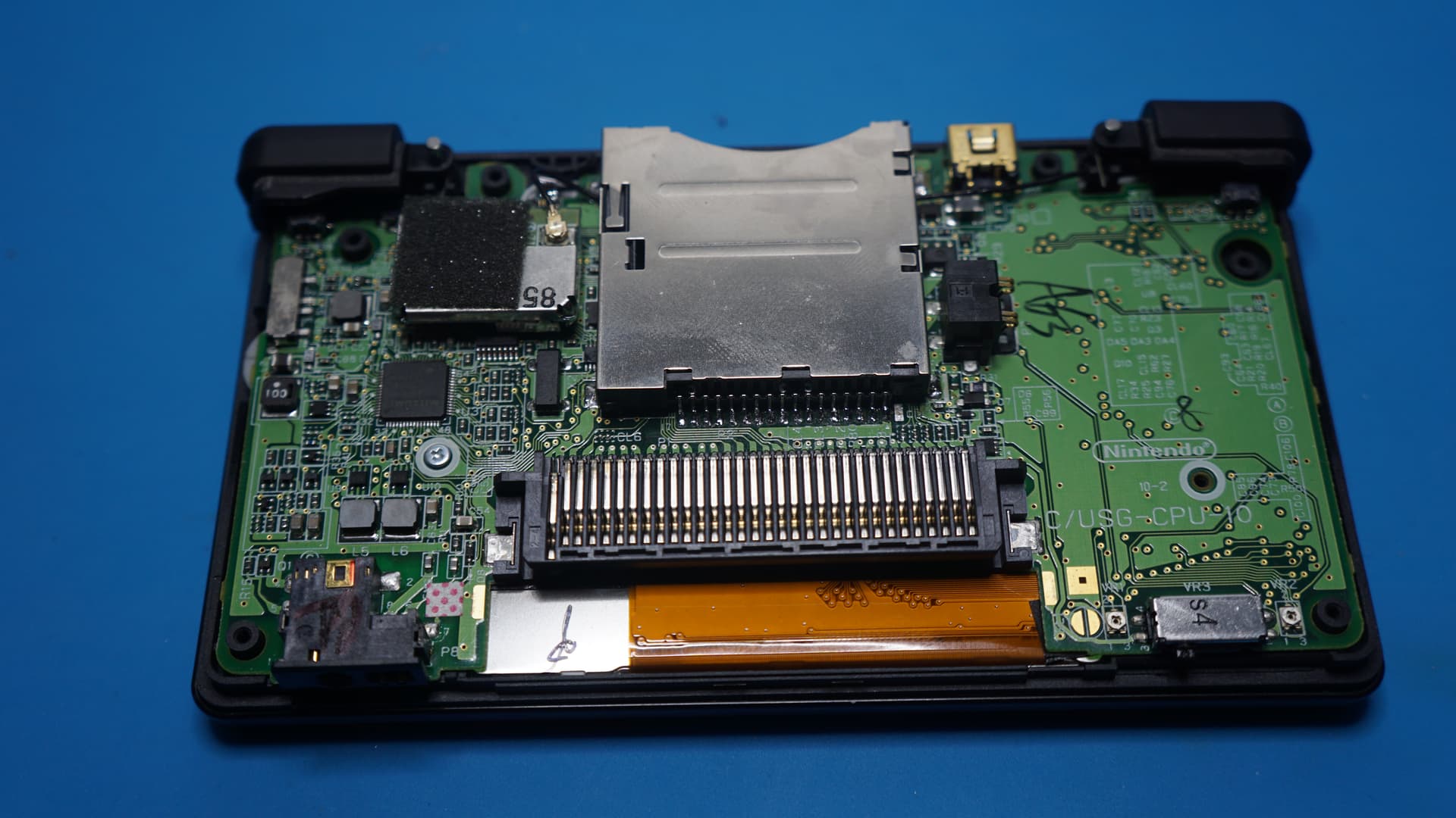
Gently you can now pry up/off the casing:

Close up of the cartridge slot we need to remove:

Because I do not want to remove the PCB fully and don’t have any need to try to save the cartridge slot, I decide to cut the pins to the rear of the slot to avoid having to use hot air:

Using solder wick I remove any excess solder from the cartridges ground solder tabs:

Using my solder iron to gently heat up these tabs I can now prise up the cartridge slot and remove it:

Since I cut the pins previously I now need to remove them with my soldering iron:

And with some more use of solder wick I clean up all the contacts:

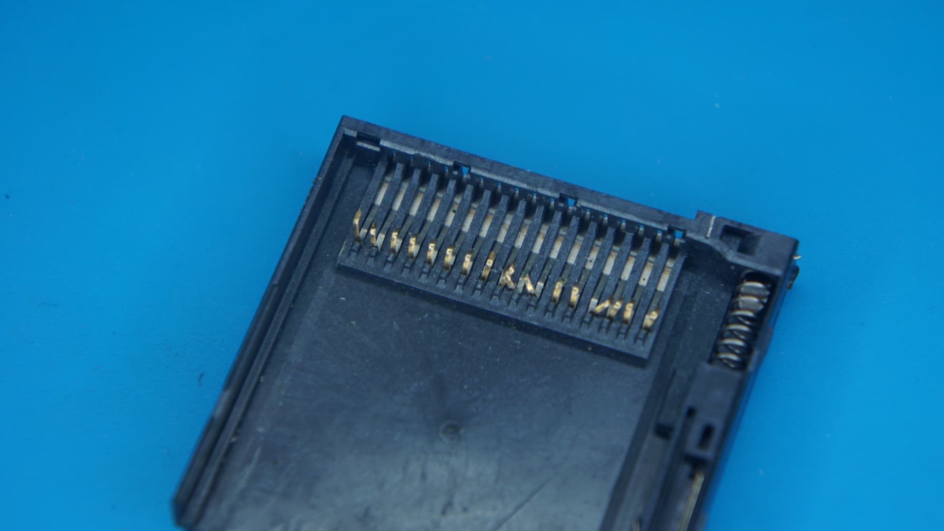
The original DS cartridge slot (right) versus the new one:

Taking off the top shielding of the original slot we can see how badly mangled the original pins are inside:
The new replacement cartridge slot is now placed into position:

And soldered onto the PCB:

I find that unfortunately I can not close the casing of the DS Lite because of two black pieces of plastic sticking out of the back of the replacement cartridge slot:

So I trim these off:
After re-assembling:

Both are now fully working again.
3 Likes
Super detailed and informative post as usual. I haven’t worked on one of these yet. Super interesting.
1 Like
I really don’t recommend it to be honest.
The third party cases tend to not be moulded very well and end up breaking the charging circuit when you close them together unless you knew in advance to file back the excess plastic inside to give good clearance over certain components.
I learned the hard way sadly… >_<
Replaced plenty of screens and touch screen digitizers in these DS lites over the past couple of years.
Found a fair few with broken charging circuits, bad internal fuses, one with a unfixable bad VDP, many with bad DS and GBA cartridge slots along with the very typical broken hinge issue.
But really as I said already they rarely feel worth the time/effort to repair and can be fiddly to deal with.
2 Likes
The pins in the original cartridge slot!!! Wow.
Great post.
1 Like
You dealt with those tabs the right way. I ended up lifting a pad when I replaced the cart slot on a DSL I bought. Live and learn I suppose!
1 Like
I haven’t done one of these in quite a long time as writing up logs and taking all the required photographs takes up a lot of time and I wanted to power through a lot of my backlog of repairs.
So let’s start us off again with something good…
A bit of back story:
So recently a lot of CPS1 arcade PCB have ended up being sold cheaply on AliExpress and while I was hearing a few horror stories, some people were getting good working boards so I decided to take the risk with a seller “Self Love” to make a test single purchase of a cheap CPS1 Motherboard to see how it would turn out as I would like to have more complete CPS1 stacks instead of having to rely on just my single working CPS1 Dash Motherboard.
So it arrives and it is an all original CPS1 Dash board! A Good start!
I then try to boot games with it and well nothing boots, I cycle through a bunch of B+C boards while testing and my Three Wonders boots up to a SCR 1 RAM NG error:

I check around the board and find many bodged trace repairs:

Corrosion on several pins of a LS253:

and suspect ram that looks like it has over heated on the right hand side:

I really was not happy with the state of this CPS1 motherboard and it simply does not work so I reached out to the seller who then made every nonsensical claim trying to get out of that they sent a broken PCB.
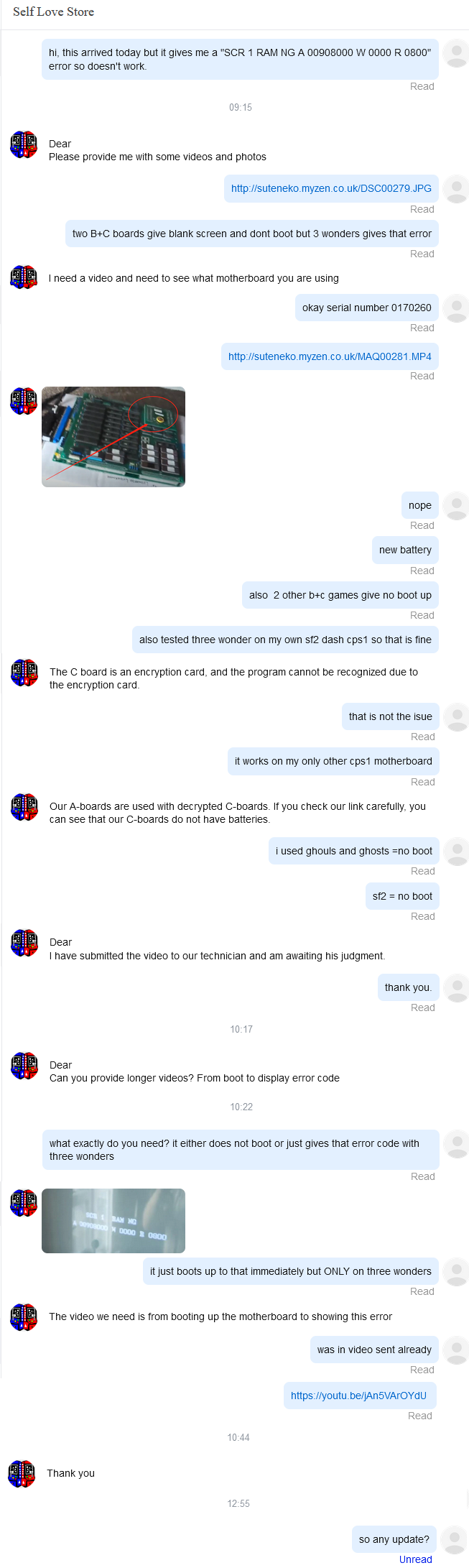
In the end they stopped talking to me and I decided to claim a dispute with them directly with AliExpress.
The sellers only response was:
DO NOT REFUND.
Buyer should close dispute and file claim with courier. We test all our products before sending.
I rejected that and after a few days AliExpress thankfully sided with me and issued me a full refund with no need to return it.
So now I can see if I can repair it.
But after eliminating the obvious visual damage I had already noted, I started looking at the potentially bad SCR Ram and pulled several of them out of circuit:

After looking up schematics for the RAM I learn they can be tested as 62256 but all three fail:

At this point this is not getting me anywhere and who knows what other issues I might run into on this trash condition CPS1 motherboard so I abandon attempts to repair it.
Not the greatest end to my first new repair log in a long time right?
Oh well…
2 Likes
Okay, clearly that was not the end.
Remember quite a while back I had a CPS1 motherboard that was also faulty and my prognosis was that it was not repairable due to a bad CAPCOM A01 custom PPU?
Check out this earlier Three Wonders CPS1 repair log to catch up perhaps?
Well clearly this Aliexpress Junk CPS1 Motherboard can display the screen correctly for at least the error screen:
So the thought was maybe I can transplant the CAPCOM A01 over to my Three Wonders CPS1 Motherboard that I figured has a bad PPU:

CPS1 CAPCOM A01 Custom PPU Transplant Repair:
So here is the trash AliExpress CPS1 Dash (12mhz CPU + XTAL) and the PPU I want:

A Lot of flux and patience with my hot air workstation later:

A very clean no bent pins pull of the CAPCOM A01 PPU:

So now onto my original Three Wonders regular 10mhz CPS1 motherboard:

A very careful Yoink and clean later:

We now have two pulled A01 PPU (Bad one on the left and marked with a B obviously):

Time to tack down the donor PPU from the junk Aliexpress CPS1 Dash into it’s new home:

Now it is in position I drag solder it onto the regular 10mhz CPS1 motherboard:

and @!#? @!#?ity @!#?ing @!#? it doesn’t boot…
Always a worry you can damage an IC from too much heat when removing them and well I wasn’t 100% sure whether the PPU on the AliExpress junker was any good either…
…
…
…
…
…
…
…
A quick solder re-flow later:

Quite happy my earlier prognosis turned out to be true and the transplanted PPU turned out to be good, otherwise all of this effort would have been for nothing…
Did I mention I really HATE QFP SMD rework?
8 Likes
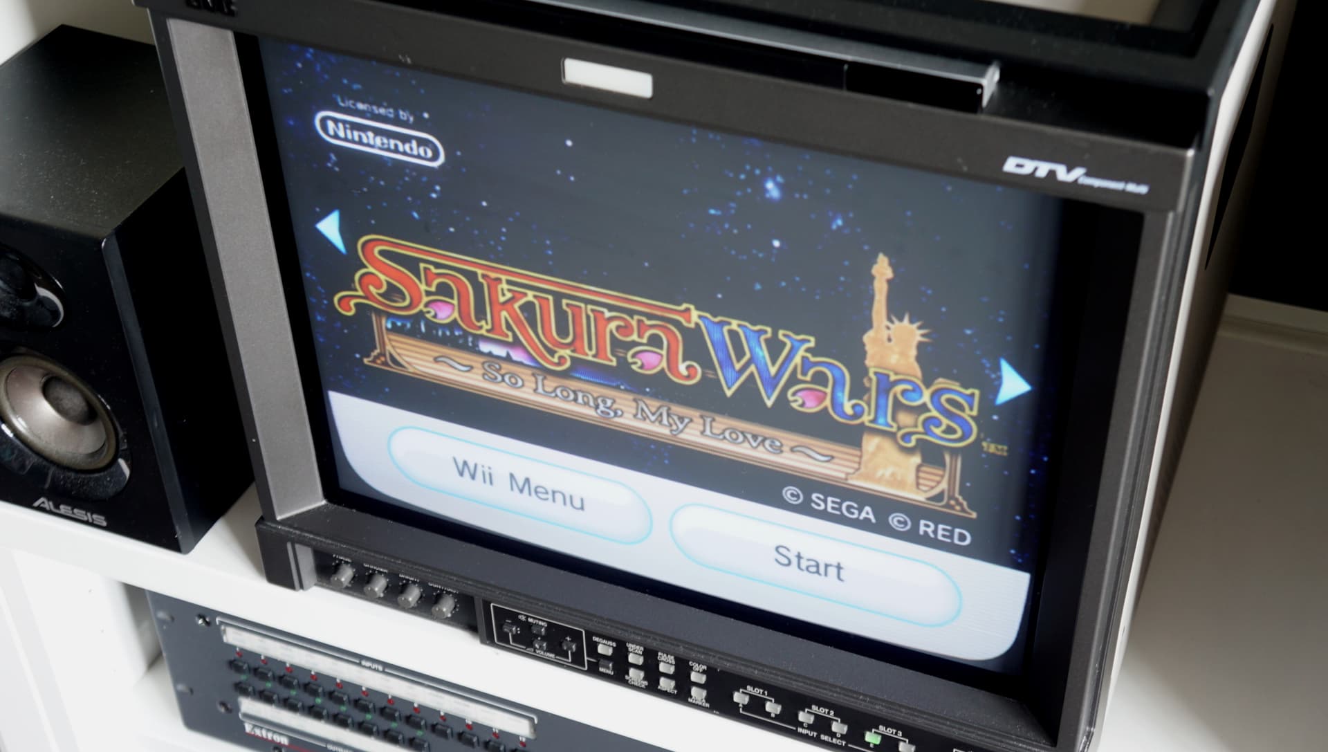
Nintendo Wii Optical Drive Not accepting Discs Repair:
A while back I was handed a Nintendo Wii that would not accept optical discs being inserted into it and that would occasionally boot up with this error:

So I opened up the Wii to see if I could find out what was going on.
After removing the optical drive can you spot the problem?

A closer look:

Looks like some child had decided to use the Wii as a money box!
After removing the top of the drive I found and removed £1.55 in change and a sequin:

Then everything was re-assembled and the drive now works fine:
7 Likes
Very cool! I somehow missed this update! I got one of these a little while back. It works but the audio circuit is a crappy rework. I wonder if it’s possible to return it to its original state. At least you know what you had. I thought I’d gotten a legit board. (They sent me one different than in the photo.)
1 Like
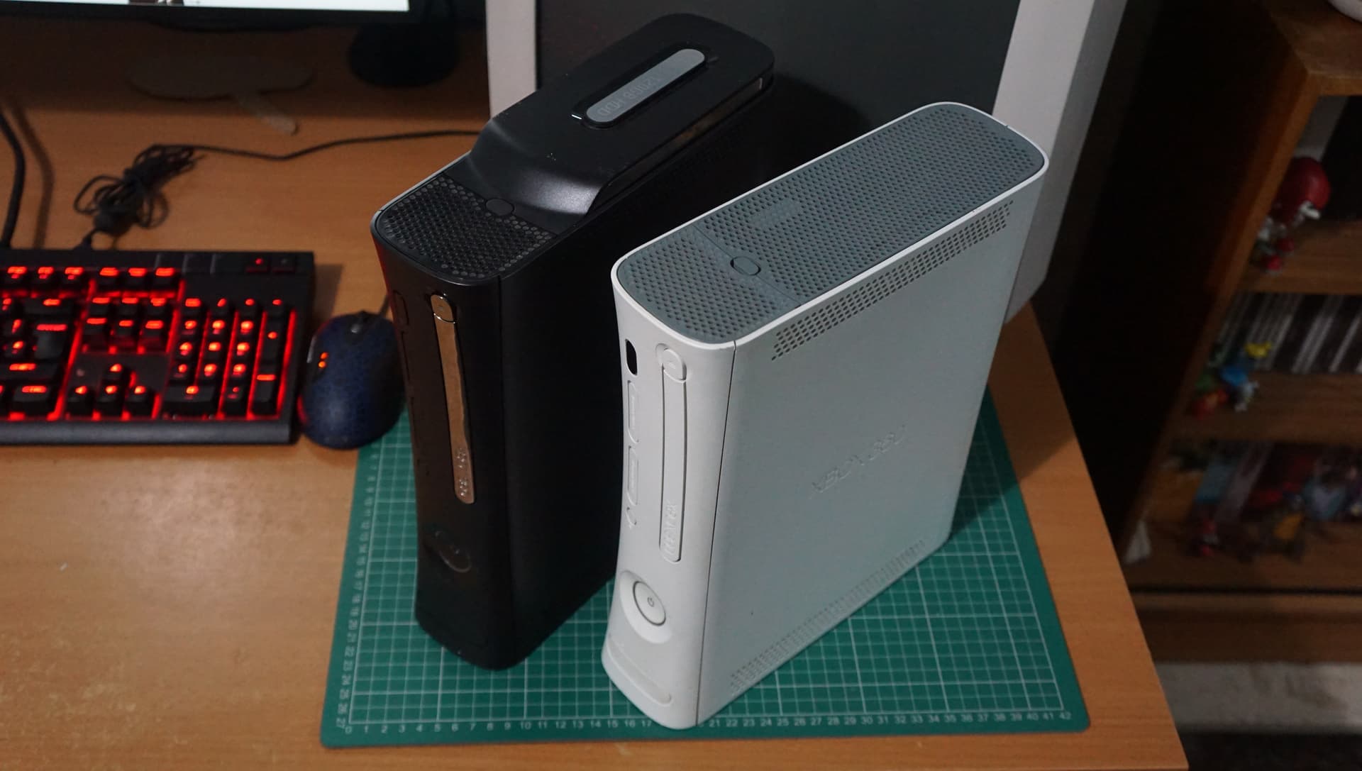
Microsoft Xbox 360 Optical Drive repairs:
I got given bunch of faulty XBOX 360 consoles earlier in the year which had been stored in my shed outside for a good while now.
Most had RROD (Red ring of Death) issues and were very early models that were not worth working on, however there was two Jasper revision consoles that booted fine but had none working drives.
The main one I wanted to work on was a Black Jasper:

Opening 360 consoles is a pain in the backside and I recommend you watch a video showing you how to do it prior to attempting it yourself. I am not going to cover the process here so we are skipping ahead:

The drive can now be removed and turn it upside down to see the 4 screws you need to remove:

Once removed you can open pull the metal case apart into two pieces:

Revealing:

This drive was not salvageable due to various reasons, so I wanted to swap in another optical drive from one of the RROD consoles.
HOWEVER, you can not just swap over an optical drive as Microsoft used a hardware key stored on the epoxied (to prevent tampering) IC on the optical drives logic board that MUST match your motherboard.
So to use another optical drive we need to swap this logic board over:

Carefully using tweezers I unclip the three ribbon cables:

Then de-solder the 6 coloured wires. I mark one of the yellow and white wires with a black marker so I know which contacted to what pad for ease:

After removing two small screws the logic board can be removed from it’s original bad optical drive:

This is then swapped onto the donor drive (there are several models so make sure they match):

Once it is soldered back in and the three ribbon cables are connected we can test the drive:

and we have one working 360 Jasper System!
The second working Jasper console had an disc tray that would not open and struggled to play optical discs.
To fix the disc tray not opening issues we need to change the drive belt.
After opening up the optical drive you can push with a small solid implement this small plastic rail inwards (as pictured below) to easily open the disc tray:

This will give us easy access to the belt:

You can see the comparison of the old (left) and replacement (right) belt below:

Now this drive just needed a laser potentiometer adjustment.
The left one is for DVD and the right one is for CD media:

These are adjusted counter clockwise in very small increments to decrease resistance.
You should take a ohm measurement over the potentiometer before adjusting anything (it should be around 5ohm) and do not go below 3ohm or you risk destroying the laser.
After a very tiny adjustment optical media started to work again:

So after working through 5 junk 360 consoles I managed to piece together two fully working ones:
4 Likes
This was one of my concerns as well. There are a lot of CPS1 motherboards that have had the audio circuit fail and Chinese resellers always seem to bodge an audio fix for as cheap and as least effort as possible. Resulting in lots of these “mangled” PCB’s being out there.
It is quite possible to revert it back to original, you just need access to the parts.
Yes they are a huge pain to open… should be illegal!
1 Like
Saisho Portable Cassette Player Repair:
I got given this Saisho BBFX12 portable cassette player to look at as it was not doing anything, the cassette door is loose and there is a rattle of something loose inside:

The owner had tried to get it running with 2xAA size Rechargeable batteries which was the first mistake as rechargeable AA batteries operate at 1.2v whereas regular AA batteries run at 1.5v and this needs the whole 3v to work.

With new regular 1.5V AA batteries inserted I can hear some grinding but nothing is actually happening… So of course we open it up:

Peeking under the PCB I can see the drive belt has dropped off:

and the rattling is caused by a loose spring that I am assuming is for the front door:

This blue wire that is attached to the positive battery terminal is stopping us looking inside:

So we de-solder it and flip the PCB out of the way to the side or at least that is what I should have done had I noticed this was possible until after I had de-soldered the wires to remove it, but hey hindsight eh?

Unfortunately the belt fell totally while doing this so I didn’t quite know how it should sit…

After some trial and error figured out the correct way to put the belt back on:

So much easier to work on when all the wires were re-soldered back in place and only the one blue wire is de-soldered to allow the PCB to be flipped to the side:

Anyway… now that is sorted I needed to figure out how to put the spring back in place.
I notice their is a hole in the door cover and try to put the spring into it:
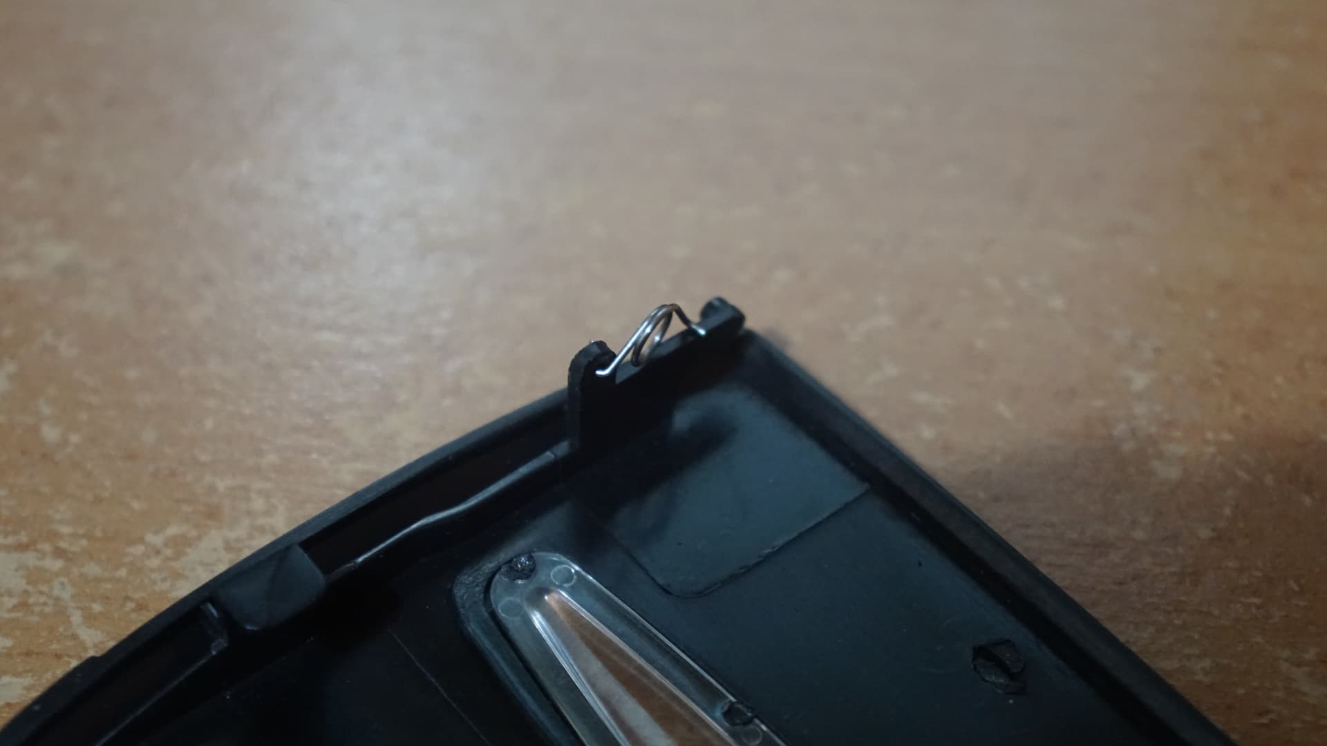
Then find a small pin hole in the case where I guess it should attach to:

Which means I need to flip the spring around and yes that is it:

The cassette door now springs closed and open correctly again!
I now re-assemble it and let’s try the demo tape I got given:
Good!
When I contacted the owner he could no believe that I had managed to get it working again and thought it would just end up being thrown away. So much so that he decided to just let me keep it for my effort made in repairing it!
And with that I have FINALLY made it to 50 repair logs!
This one was a bit off topic for the boards but I have a bunch of other logs to put up all retro game related in the near future.
6 Likes
Love it! Auto reverse AND a radio was the ultimate in luxury back in the day. Absolutely baller as hell to roll around with one of these on your belt ![]()
3 Likes
So cool! Congrats on another great repair.
2 Likes
TIL rechargeable AA’s are 1.2V. I’ve been using them in a lot of stuff recently …seemingly without issue so far ![]()
I always enjoy your posts, thanks for continuing them! They seem like a lot of work on top of the actual work.
3 Likes
Yep, really depends on the device. Modern devices are mostly OK. Older devices not so much. Check the label. Most recently my Psion Series 5 doesn’t operate correctly on rechargables, it’s battery remaining power curve is hard coded for alkaline 1.5v.
2 Likes
Thank you for the kind words @dubc!
Sometimes the write up ends up taking longer than the actual repair but usually it is a couple of hours work to get everything in order to post up a new log.
Of late I haven’t written up as many repair logs as I really could have, even though I often take photographs for reference during a lot of repairs/mods and have plenty I could write up that I never got around to doing.
Hard to gauge if there is interest and sometimes I just want to clear backlogs faster by omitting the extra steps.
Thanks @Peltz! I almost did not post a repair log up for this Saisho portable cassette player repair but felt like for the 50th log it had to be something a little different to past repairs and I wanted at the very least to reach the 50 number before the new year.
3 Likes
The most useful IDE Optical Drive ~ A Hitachi GDR8163B Repair:
For those of you that are not aware, it is actually possible to dump Gamecube and Wii games on a PC using RawDump if you own one of a few very specific models of LG/Hitachi IDE optical drives.
While a few other LG/Hitachi optical drives have been found to work in general you are only guaranteed success with the the following models and even that may depend on the firmware installed on the drive:
LG GDR-8161b
Hitachi LG GDR-8162b
Hitachi LG GDR-8163b
Hitachi LG GDR-8164b
Full list of tested working/failure drives for this purpose can be found here.
The other use of specifically the Hitachi GDR8163B Optical Drive is that it can also be modified to work as a replacement Original XBOX drive (See here).
I’ve had a working Hitachi HL-DT-STDVD-ROM GDR8163B0B26 drive for the purpose of dumping my own discs in my Windows XP PC for quite a while now.
However, I had ended up with several other Hitachi IDE drives salvaged out of junk PC over several years and finally got around to looking through them to test if any of them would work.
Almost everything was failure however there were two drives that had potential:
A highly likely to work Hitachi HL-DT-STDVD-ROM GDR8163B0F21:

and a much less likely Hitachi HL-DT-STDVD-ROM GDR-H30N:

The Hitachi HL-DT-STDVD-ROM GDR-H30N as expected didn’t work.
So I moved to test the GDR8163B0B26 which I already knew had a faulty drive belt because the disc drawer would not open.
If you look carefully on most optical drives you can find a small hole underneath the drive door which I have circled in the picture below:

By inserting some long and thin into it you can force the drive open:

I could now pop in a disc, however to my dismay I found the drive would not read any optical media.
So I decided to open up the drive to see if there was anything I could do.
To do so I had to pop the drive drawer back open again:

With this now open you can find some tabs to the sides that hold the front panel in place:

With a careful little prying you can pop the front panel off:

Then flip the drive upside down and unscrew the 4 screws:

After being flipped back the right way around you can then just lift up the metal casing and we can take a closer look at the laser which has the model number: SF-HD68

Out of curiosity I decided to open up the worked (but no good for game dumping) GDR-H30N and find it has an almost identical laser but with the model number: SF-HD68 V2 and the only difference I can spot is that the plastic piece that connects to the drive shaft is fastened to the bottom of the laser instead of the top:

I decide to attempt to swap these lasers, so going back over to the GDR8163B0B26 I need to remove the two black screws circled below:

DO NOT adjust or remove any of the other screws or you will enjoy the pain of having to try to re-align the drive and you really do not want to have to do that!
You can now pop off that metal plate, disconnect the flex cable and lift up the left metal guard rail to easily remove the laser housing:

With the laser now removed the white plastic piece is detached:

I then remove the other laser and remove it’s bottom connected white plastic piece:

Thankfully these plastic pieces are interchangeable between both models of laser, so I swap it over to the working laser and then place it into the GDR8163B0B26:

Before closing everything back up I replace the drive belt.
Now I can test the drive again:

And the drive is working again!

So it would seem the lasers found in the newer not compatible (also not sought after) Hitachi “GDRxxxx” optical drives can be used to repair a dead laser in a good Hitachi “GDR8163B” DVD-ROM.
Good to know!
Excuse some wonky and not the most ideally suited photographs in this post as when I started I thought I was just going to be doing a simple drive belt replacement… So they were taken after most the work had already been done.
3 Likes