SEGA System 16b 171-5797 ROM Board Repair:
This is a follow up to a previous “repair” where I found this E-Swat 171-5797 ROM board to be faulty:

Any time this ROM board was inserted into a working SEGA System 16b Motherboard you would get a black blank screen and no sound.
While looking around the board originally I had discovered that the axial salmon coloured non-polarized capacitor at C109 had a small crack across it and when pressed very lightly broke away:
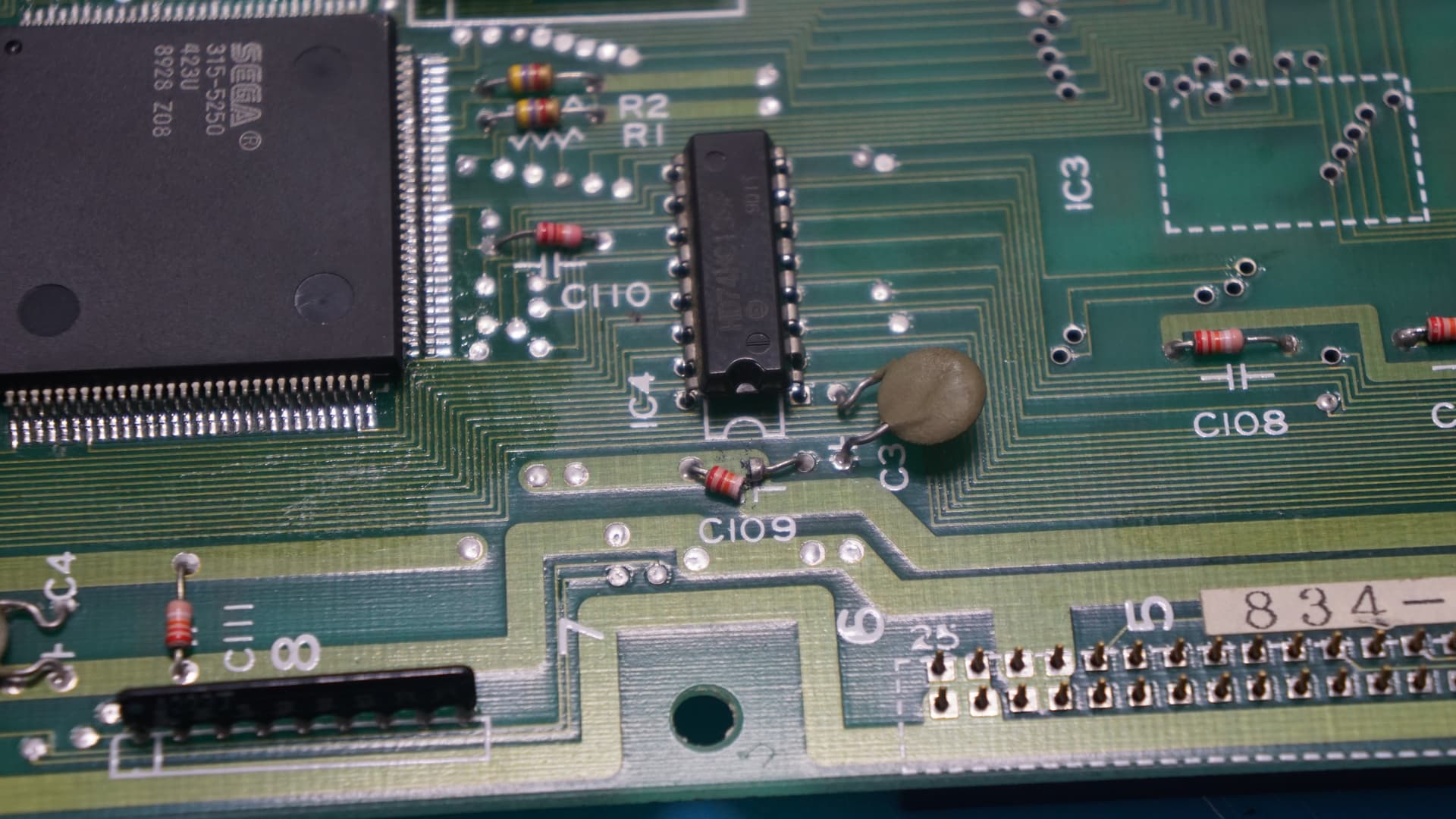
I couldn’t find anywhere to buy replacements for this sort of capacitor and put it to one side to look at properly some other time.
Recently I was salvaging parts from some old spare junk VCR PCB’s and lo and behold noticed they were using the same type of capacitors which jogged my memory about this ROM board and de-soldered a bunch of them, of which a fair few were the exact same banding as the one I needed to replace:

I didn’t expect this to be the end of the problems and sadly that was the case the board was still dead.
I decided to test the 4 470µF and 1 x 4.7µF capacitors and while their capacitance measured fine their ESR while not bad enough to stop them working was a little high so I replaced them all anyway:

Again as expected this didn’t change anything and the board was still not working.
So I got at my logic probe set to TTL level and started probing around the board while it was turned on to see if I could discover what was going on.
I had correct activity on all the SOUND and Graphics ROM, however I was getting zero activity on any of the input and output pins on the Program ROM :

These Program ROM are 27C2001 EPROM and to test farther I needed to check if they were getting power and connected correctly to ground:

VCC is the 5v power input pin which is on pin 32
VSS is the Ground pin which is on pin 16.
For those curious VPP is for the re-programming voltage input and can be ignored here.
Using my multi-meter I was able to confirm 5v was present and the ground was also connected properly.
These Program ROM are connected to two custom QFP SEGA IC (a SEGA 315-5250 and a SEGA 315-5248 on the solder side of the board) and a HD74HC139P 74xxxx Series TTL Logic IC.
The solder on the custom SEGA IC didn’t look the greatest but had no visible continuity issues.
Regardless I re-flowed their solder just to be on the safe side:

No change, so I de-soldered the HD74HC139P and went to test it in my Universal Programmer:

It tested good so got soldered back onto the PCB.
So now I either have a bad custom SEGA IC which can not be replaced or a broken trace somewhere.
I start to have a much closer look all over the PCB under magnification and eventually notice this:

Unfortunately the 3 traces go underneath the IC2 located Program ROM so I had to remove the EPROM and the socket to be able to test these 3 traces properly:

Using the continuity mode of my multi-meter I discover that the top 2 traces are still fine however the trace that connects to PIN 2 of the Program ROM (Address line 16) is broken.
Usually here I would scrape away the solder mask a little around the break and re-connect the trace with some thin gauge wire, however at present I don’t have a fibreglass pen at hand so I had to resort to a bodge wire which i placed on the underside of the ROM board:

And working again:

Since this is a repaired ROM board and because I already have a working E-Swat ROM Board I am tempted to convert this into another game (possibly Golden Axe) in the future.