As I posted in the pick-up thread, I recently bought an MVS MV1C for a decent price. I already own an MV1FS, but it’s kinda large - and the MV1C is significantly smaller.
I was planning on having an enclosure built out of wood, but I’ve since changed my mind and decided to go with this aluminium enclosure by Hammond (http://www.hammondmfg.com/1455.htm), specifically the black model 1455T2201BK which is a fantastic fit for the board. You can see the red variant used as a CMVS enclosure here: http://www.mmmonkey.co.uk/neo-geo-mvs-mv1c-consolisation-cmvs/
I quickly hooked up 5v and video the other day, just to check it worked - and it does:
Rather than hooking up the RGB lines straight to the video output, I’ll be doing it correctly by dropping the 3v lines down to 0.7v and then feeding them through to the THS7316 amp (commonly used in SNES/N64 mods). This results in a perfect spec output, same as what the AES does with the same initial video.
I’ll be also building my own Neobiosmasta which allows the easy install of a unibios. I’ve ordered the boards from oshpark as per usual and they were fabricated and dispatched to me last week.
So all going well, I should have this project done within the next two weeks. I’ll keep this thread updated with progress. Feedback and ideas would be appreciated!
I haven’t got any links to hand, but I found a fair few sources on assembler games and elsewhere stating so, and it was verified too. I’ll be checking with my multimeter tomorrow anyhow to make sure.
Not sure about the output voltage off top of my head post amp, would have to look at the datasheet. But in any case it’ll be exactly what the display is expecting I hope, and with the correct 75ohm impedance
Sync won’t need any attenuation, it’s fine as is from what I’ve read, but again I’ll check it out when I have time tomorrow. The sync is quite strong, so there’s no need messing with it. Stronger is better with sync!
Getting excited about putting all this together! I think the main trouble I’ll have is the cart slot - but with my Dremel, a decent file and a good amount of wet/dry sandpaper it should turn out nicely.
Just tested out the MVS video lines on my multimeter - definitely confirms what I had read previously, which is cool. I’ll continue with the RGB amp circuit. I’ve had to order the THS7316 from China, so if it hasn’t turned up by the time I get the rest ready I’ll use one of the THS7314s I have lying around (THS7316 has a sharper image due to no low pass filter) and swap them over after.
One thing that I wasn’t expecting was that the csync line measured at 5v…
That’s uh, a bit much. The SCART spec advises 1v on the sync line: http://martin.hinner.info/vga/scart.html and anything higher could damage equipment. So I’ll be knocking that down too.
Bear in mind these boards are built for specific arcade setups and not home electronics, nor units such as the OSSC that run on much lower voltages. All the CMVS tutorials I’ve read gloss over this and just recommend hooking directly up to the SCART socket which is a bit concerning…
Casing is being delivered tomorrow, hopefully it will look as good as I hope!
This would be my ideal way to get a neo geo in my home. I still think I would rather have a CPS2 but there are enough neo geo games I would like to have that I am going to follow this thread out of curiosity.
Yeah it’d make sense. Definitely would advise anyone with a CMVS to double check what it’s outputting. Those built with an amp circuit with sync dropped to the right voltage or a neobitz should be ok though.
Edit: got the case today! Gonna be a real tight fit…!
I have seen people make a horizontally mounted cart. Is that standard? Or are people modding the main board for that. I don’t have anymore vertical space in my set up area. everything has to be short.
Problem is, making an enclosure for those is tricky. Whereas with a top loader, you just need a decent enclosure and Dremel out what you need. This is the one I got:
My Dreamcast, Saturn, and analogue nt (when using rgb) are always swapped in and out when I need them. I could fit the top loader in the same spot but I would always have to remove it when I want to play my snes. I need to redo my gaming set up but since I my crt and retro consoles in my office closet to keep out of sunlight and to avoid the ire of my wife. The problem is, to redo my set up. I am going to need to tear out the old closet and I just haven’t decided how I want to fit everything back in. I also need to have a TV stand that can hold about 300 lbs just in case I have a few crts.
It literally slides in. Which is good in some ways but it does mean that I’ll have to mount the DC socket/RGB/power switch underneath the board at the back. Just means the cart will stick out higher. The screw posts will need some tinkering with too.
Edit: hm, I will have enough room for power and RGB at the back, but maybe not the power switch…I may have to put that at the top. I’d rather not though.
Next update will be with the RGB amp circuit board built and then it’s wiring the ports and mounting in the shell. Everything’s kinda waiting on the Neobiosmasta boards from the US though.
Edit: they arrived! And I have an evening without the daughter or girlfriend around tonight. As soon as I get back from work, I’ll start wiring everything up.
Oooo you couldnt have timed this better, I have a spare MVS and really want to consolise it… so this is brillient and I will be reading with great care… thanks for posting this…
I’ve put together the Neobiosmasta. Hooked it up and it works fine! Idiot me thought it was broken at first Windjammers wouldn’t boot past the unibios screen…I had the pause dip switch toggled on. Derp.
Looks like I’ll have to skip the amp. I have absolutely no idea why, but I cannot get a stable image with it, even with untouched sync. Maybe the one I was using was fucked, but I spent so long messing with it last night I’ve decided to move on
I’ve just used a few resistors to get the lines down to the right level instead. Works fine. Eh. If I get time tomorrow I’ll start on the casing and finish it off.
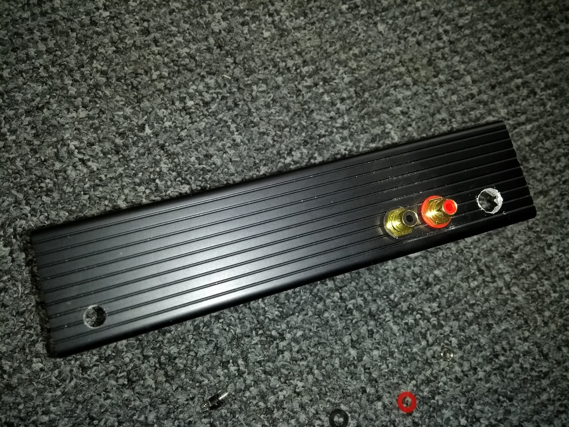
And another…RGB and power added to the back, one port done at the front with an led to go in-between. Break for now! Almost done. I also wired up both controller ports, and they work fine.
I have got quite a bit of “snow” noise on the video which wasn’t there before. I’m not sure whether it’s due to the scart cable I hacked together for it but there’s definitely a ground loop somewhere.