Panasonic DMR-EZ48V DVD/VCR Combo Repair:
This is a little off topic for these forums but I hope some of you will find this interesting and potentially helpful for trouble shooting problems in other older electronic devices.
I bought this really lovely Panasonic VCR/DVD recorder combo unit about 7 years ago:

It has been powered on 24/7 for the entirety of that time, with it being used as my main method of watching VHS and DVD as I can output VHS and DVD content over component using it.
However recently I started to slowly notice I was getting some noise in the video which over the next few days got rather bad and was manifesting as horizontal noise lines in the video that sometimes would go bright orange along with a nasty hum in the audio.
I attempted to get at least one photograph of the issue but sadly this was the best I was able to manage as I really didn’t want to keep it powered up much longer:

I originally picked this up for £5 but now days they are apparently quite sort after (especially I suppose as they can record digital broadcast TV direct to VHS and output it easily to any CRT) and they are now selling for some serious money online.
I really wanted to save my unit so I decided to dismantle it to see if a repair would be possible.
Let’s start!
Taking the top off was rather simple, just remove a few screws and pull it off towards the rear:

Then you have to remove a single screw and unclip 5 clips to remove the front of the unit:

After removing 3 more screws you can flip the DVD drive over to the side:

Carefully pull out the 4 ribbon cables from the PCB underneath to allow you to remove the optical drive:

One more ribbon cable needs to be disconnected (the one that goes to the HDMI output) and after a few more screws are removed this PCB can also be pulled upwards to be removed:

This reveals the whole of the right hand side PCB, which the majority of which (upper right) is a switched mode power supply. Looking closer we can see some capacitors along the power rails are leaking:

I suspect this is the main culprit for the issues!
But first we need to remove this PCB and to do this we need to remove some screws from the rear of the unit that secure the input/outputs of the the machine:

Then very carefully I had to pry up these strange clips (one out of picture) that connect both main PCB:

After removing a few more screws and disconnecting the fan I could then remove the right PCB:

Since I had opened it up this far already I decided I would also check out the PCB to see if it also needed some refurbishment as this PCB controls the VCR and the main video/audio circuits.
The VCR unit was held in place by 5 screws which needed to be removed and the two ribbon cables for the video and audio heads needed to be disconnected at the motherboard before you can pull the whole thing upwards and off the motherboard:

Even more screws removed later and we are fully disassembled:

Sorry Johnny Five:

After removing the HDMI unit from the PSU/DVD motherboard PCB it is now ready for testing:

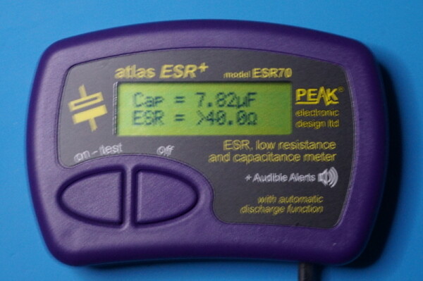
Using my ESR meter I started to test and compile a spread sheet of all the capacitors on this board while they are in circuit to give me a better idea of the situation.
Note:
Testing in circuit while in most cases will always give you the ESR reading for the capacitor.
However if the capacitors are in series with each other then you can end up with a combined ESR/Capacitance reading and it is common for you to not be able to get and capacitance reading due to nearby components.
Using some coloured ZEBRA marker pens I then marked the top of every capacitor to give me an easy visualization of where work needed to be done.
LEGEND:
- RED = BAD
- GREEN = GOOD
- PURPLE = Can not fully check In-Circuit

From this it was easy to tell that the majority of the HOT and COLD sections of the PSU part of this PCB needed to be replaced. All the capacitors that could not be tested properly in circuit were removed and tested out of circuit and the results were conclusive that only the capacitors on the power rails needed replacing.
In total 15 capacitors were replaced:

Moving over to the left side VCR/AV PCB the same was repeated after un-slotting the small PCB on its left that does the decoding of video/audio streams.
Quite a few capacitors here were measuring with high but still just within acceptable tolerance ESR so I marked these with an ORANGE marker pen, but after checking some of them out of circuit I decided that the majority of them were fine and ended up only replacing 10 problematic reading capacitors:

These two PCB were then placed back into the housing:

Before dropping the VCR unit back onto the PCB we have to ensure that this cog is aligned correctly with the marking on the PCB:

We can then slowly start to re-assemble everything back together:

However, we are not quite finished yet.
I still have the slot in encoding board to check:

SHIT:
All the SMD electrolytic capacitors on this are measuring with VERY BAD ESR…
I had never been able to get digital freeview TV broadcast to sync up with this so I could try to perform a firmware update, but I didn’t really ever care as I don’t watch TV and just assumed some incompatibility with the current broadcast system. But this leads me to believe that this was why!
So I needed to carefully use hot air to remove these SMD capacitors…

and replace them with new ones:

This was then slotted back into the unit so we are ready to test it and we appear to be working:

Here is all the removed and replaced capacitors:

I then tried to hook it up to an aerial and I was now able to do a firmware update check successfully:

All the noise is gone from the video and audio now:

For those interested here is the spreadsheet I created for this Panasonic DMR-EZ48V Recap Project.
Doing a full recap of this would have been cost prohibitive and wouldn’t have let me discover what exactly was problematic.