SEGA Game Gear (837-9130) 1 ASIC Refurbishment:
I was recently able to pick up another Game Gear in a bundle from a dumpster diver:

As expected the Game Gear has issues, but at least it powers up and has sound (albeit very low volume):

At the bottom of the original Game Gear screen you will find three IC that are embedded within the plastic housing. These IC are LCD driver chips and if their internal connections start to fail you will get a dark 1/3 portion of the screen per failed IC.
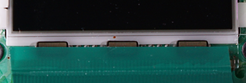
Pressing down hard on the center IC removes the dark section of the screen:

However, as soon as you remove pressure the middle section of the screen goes blank again. You can try hot air to try to re-flow the internal connections but unfortunately this was not working for me and coloured vertical lines on the screen usually mean a new screen will be required anyway.
Checking inside we can see some previous liquid ingress damage, fortunately without any corrosion:


So this goes onto my workbench for a recap, screen replacement and general clean up:

Motherboard Capacitor Summary:
![]() C1 - 33µf (6.3v) ~ TESTED: 490nf and LEAKING
C1 - 33µf (6.3v) ~ TESTED: 490nf and LEAKING
![]() C4 - 10µf (6.3v) ~ TESTED: 9.01µf
C4 - 10µf (6.3v) ~ TESTED: 9.01µf
![]() C11 - 10µf (6.3v) ~ TESTED: 6.5µf
C11 - 10µf (6.3v) ~ TESTED: 6.5µf
![]() C14 - 10µf (6.3v) ~ TESTED: 10µf
C14 - 10µf (6.3v) ~ TESTED: 10µf
![]() C42 - 10µf (6.3v) ~ TESTED: 10µf
C42 - 10µf (6.3v) ~ TESTED: 10µf
![]() C43 - 22µf (6.3v) ~ TESTED: 7.5µf
C43 - 22µf (6.3v) ~ TESTED: 7.5µf
![]() C45 - 4.7µf (35v) ~ TESTED: 4.2µf but LEAKING
C45 - 4.7µf (35v) ~ TESTED: 4.2µf but LEAKING
![]() C48 - 68µf (6.3v) ~ TESTED: 0.88µf and LEAKING
C48 - 68µf (6.3v) ~ TESTED: 0.88µf and LEAKING
![]() C49 - 100µf (4v) ~ TESTED: 126µf and LEAKING
C49 - 100µf (4v) ~ TESTED: 126µf and LEAKING
![]() C54 - 0.47µf (50v) ~ TESTED: 2.48µf and LEAKING
C54 - 0.47µf (50v) ~ TESTED: 2.48µf and LEAKING
![]() C55 - 0.47µf (50v) ~ TESTED: 3.10µf and LEAKING
C55 - 0.47µf (50v) ~ TESTED: 3.10µf and LEAKING
![]() C68 - 100µf (6.3v) ~ TESTED: 122µf
C68 - 100µf (6.3v) ~ TESTED: 122µf
Power Board Capacitor Summary:
![]() C5 - 22µf (35v) ~ TESTED: 23µf but LEAKING
C5 - 22µf (35v) ~ TESTED: 23µf but LEAKING
![]() C11 - 100µf (25v) ~ TESTED: 117µf
C11 - 100µf (25v) ~ TESTED: 117µf
![]() C13 - 820µf (6.3v) ~ TESTED: 858µf
C13 - 820µf (6.3v) ~ TESTED: 858µf
Audio Board Capacitor Summary:
I was unable to test any of the 5 capacitors on this PCB because they were all BADLY LEAKING electrolytic fluid and I didn’t wish to risk damaging the solder pads so I used flush cutters to cut the capacitors clean off and only then removed the remains of the smd capacitor legs.
I then had to resort to using a Fibreglass pen to clean up corrosion:

After everything was re-capped I tested the Game Gear again, but it was not powering on…
I found the issue was that the 1.28v supply wire was sometimes shorting to Ground inside the connector:

Because the short was inside the connector header I had to cut it off and re-solder the wires to the motherboard manually, which fixed the problem and the Game Gear now powered up again.
I then removed all the no longer required components for a new screen installation and replaced several SMD components using my hot air station as the new screen requires some different resistor values:

Replacing the Screen:
I really wasn’t willing to pay the price of another genuine McWill Game Gear Screen and I knew Chinese clones of it had appeared and were available to purchase for up to half the price.
While looking on AliExpress I came across a Funny Playing Version 2.0B Clone screen that advertised among other things:
- Power saving design with DC-DC power supply chip.
- Adjustable Brightness Control
Which got me intrigued as the genuine McWill does not feature any of these and this appeared to be a dubiously “improved” version and not a mere clone so I bought one:

This arrived from China to the UK in only 4 days time and was very well packaged.

Unlike the genuine McWill the screen does not come pre-attached to the screen logic PCB.
Straight away you can notice that this PCB is much thinner, has smaller (and not gold flashed) solder pads and uses smaller SMD (but better rated) voltage regulators.
That said the clone is much better labeled and uses faster rated ram:

Some wire is provided which appears to be solid core 32 or 34 AWG wire. While I did use this as I could thread it easily behind the screen, I think it would be better to use 28 AWG wire instead which I did for the Clock, Sync, Ground and voltage wires as they are the most important.

I almost forgot to connect a wire from T10 to R23!
This small connection is only required for Sega Master System games to display correctly:

Since the screen does not come pre-attached you need to buy some double sided sticky pads with which to affix the screen after everything is installed:

This does make aligning the screen a bit more difficult, but as long as you don’t press the screen down you will be able to gently pry it free to adjust its position.
I then finally attached the two wires required for brightness control to function:

Everything was then re-assembled.
It is rather difficult to show the comparison of brightness settings in photographs but I tried anyway.
Please note that in person the difference is much more pronounced.
Lowest Setting:

Highest Setting:

Personally I can not tell any difference between this clone screen and a genuine McWill.
Hopefully McWill updates his design to include brightness control in the future.