SEGA Mega Drive PAL VA4 Refurbishment & Modding:
The Very Amateur Past:
One of the very first mods I tried to do when I was starting to get back into retro gaming in 2015 was putting a region switch on my Mega Drive, which is a rather simple mod and because of this a good mod for beginners to attempt.
I had no soldering experience and I was using cheap and nasty tools, but it worked and gave me enough confidence to later the same month remove the RF modulator to allow me to add a rear stereo audio jack to my Mega Drive so I would no longer have to have a cable reaching round the front of my Mega Drive to obtain stereo audio output.
The results obviously weren’t the greatest…
Poor solder joints, bad wire choice and barely soldered in frayed wires that could potentially short out:
I’m not even sure now how I even managed to remove the RF Modulator without damaging the via’s as I didn’t even know what de-soldering braid or pumps were then:
I ran speaker wire directly from the front stereo jack connections with no care about interference to the rear of my Mega Drive and didn’t bother to clean up any flux:
I then also did a bad job of connecting ground to the stereo jack via a capacitor leg:
Perhaps due to my mechanical engineering background I am fortunate that I choose good placements for my region switch and rear stereo jack and did very clean installs of them:
Starting Fresh:
In 2019 I decided I would properly refurbish my Mega Drive.
All the previous mods were removed, flux residue was cleaned up and via’s properly de-soldered.
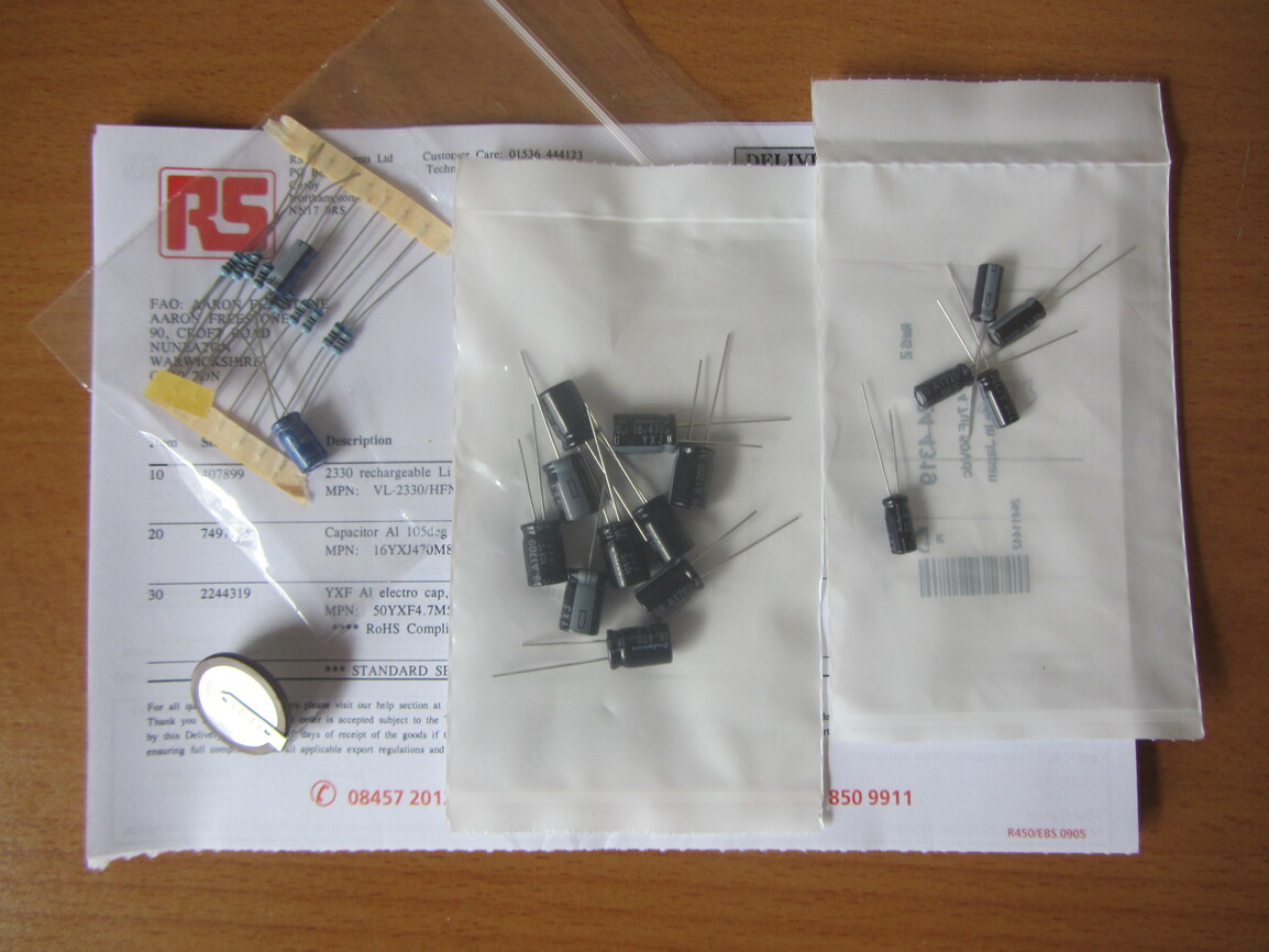
PAL VA4 Mega Drive Recap:
After testing each individual capacitor as I was removing/replacing them I could see that every 100µF & 220µF value capacitor bar one at position C79 was capacitance testing outside of specification tolerances and all the 47µF capacitors were all just on the borderline of the 20% tolerance.
Summary
 C01: 220µF 16v 8mm
C04: 100µF 10v 5mm
 C05: 10µF 16v 5mm
C13: 10µF 16v 5mm
C23: 100µF 10v 5mm
C24: 100µF 16v 5mm
C30: 10µF 16v 5mm
C31: 10µF 16v 5mm
C32: 220µF 16v 8mm
C38: 10µF 16v 5mm
C40: 1µF 50v 5mm
C41: 10µF 16v 5mm
C42: 1µF 50v 5mm
C43: 10µF 25v 5mm
C44: 1µF 50v 5mm
C49: 100µF 16v 5mm
C50: 220µF 10v 6.5mm
C51: 220µF 10v 6.5mm
C52: 100µF 16v 5mm
C53: 100µF 16v 5mm
C55: 10µF 16v 5mm
C57: 10µF 16v 5mm
C58: 1µF 50v 5mm
 C59: 47µF 16v 5mm
C60: 47µF 16v 5mm
C61: 1µF 50v 5mm
C62: 1µF 50v 5mm
C63: 47µF 16v 5mm
C64: 10µF 16v 5mm
C65: 47µF 16v 5mm
C66: 47µF 16v 5mm
C67: 47µF 16v 5mm
C68: 47µF 16v 5mm
C71: 10µF 16v 5mm
C72: 10µF 16v 5mm
C74: 100µF 16v 5mm
C79: 100µF 16v 5mm
C86: 100µF 16v 8mm
Replacing some Additional “Optional” Components:
I then also replaced the two original 7805 voltage regulators with more efficient 78S05 voltage regulators and because this Mega Drive is used essentially 99.5% of the time in NTSC mode I removed the original PAL 53.203MHz clock crystal (OSCI):
and replaced it with an NTSC 53.693175MHz clock crystal so I could get exact timings for 60hz:
Re-Tension Cartridge Connector Pins:
By using a small flat headed screw drivers I very gently applied a little bit of pressure to each of the cartridge pins to increase the tension as they were a little loose from years of abuse:
Region Modding the VA4 Mega Drive:
On the Mega Drive you will find 4 sets of jumpers labeled JP1-4.
Simply JP1 & JP2 control language, JP3 & JP4 control video output and the regions are set as follows:
| REGION |
Language |
Video |
| JPN |
GND |
+5V |
| USA |
+5V |
+5V |
| EUR |
+5V |
GND |
To get a blank state on a PAL Mega Drive you need to cut the traces between JP3 & GND and JP2 & +5V:

For reference:

For a cleaner install and better routing I decided to run my wires underneath the Mega Drive and thread the wire through the via’s and soldered them on the topside of the PCB:
Using a DPDT ON OFF ON switch we want to connect it up as follows:
- Left: JP4 or JP3
- Middle: Ground
- Right: JP1 or JP2
We then want to connect both the left and right terminals with 1.2K ohm resistors that are in turn tied together at the other end and connected to 5v to create a pull-up resistor so that when the language or video jumpers are not connected to ground through the switch they are “pulled” up to 5 volts.
NOTE: Instead of using a switch you could also try a switch-less mod
Adding a Halt Switch:
If you connect pin 17 of the 68000 CPU to ground the CPU will halt and stop running. This is great to be able to freeze the Mega Drive where you would usually be unable to pause and to be able to get a clean screen in those games that obscure the screen when paused.
So by connecting a SPDT ON/ON switch as follows we can have a halt switch:
- Left: Floating
- Middle: Ground
- Right: CPU Pin 17
NOTE:This switch will not pause SEGA Master System games as they use the Z80 CPU.
Since I had previously installed a region switch which I had positioned to the left on the lower case house, I just needed to drill and file a second hole for this new second switch:
Again I routed the required wire from the 68000 CPU pin 17 underneath the PCB and piggy backed the ground from the region select switch.
Both Switches installed:
Due to the positioning and using slide switches, both switches are well hidden but easily accessible:
Installing a M1 Mini Mega:
To improve my Mega Drive’s audio output I decided I would install a M1 Mini Mega PCB:
Since I already had a stereo audio jack installed I hooked its audio output up to that.
NOTE: The caveat of using a M1 Mini Mega is that the volume slider is now sadly non-functional
Widening the Cartridge Slot:
So I could insert Japanese cartridges without the need of a pass through adapter I decided I would widen my cartridge slot by using a fine file and linishing paper to remove the bare minimum required:
With a Japanese cartridge inserted:
Additional Information:
VDP Pin 50:
Pin 50 of the SEGA 315-5313A is the video sub-carrier (marked in pink) and due to it running very close to the RGB line can cause video interference especially along the Blue line.
VDP pin 50 and RGB traces PCB top side:
VDP pin 50 and RGB traces PCB bottom side:
You can optionally lift leg 50 of the 315-5313A to remove this interference, however you will then be unable to use composite video for the dithering.
SONY CXA1145P:
If you wish to fully convert a PAL Mega Drive into a NTSC machine you will also need to lift Pin 7 of the CXA1145P and connect it to +5v. This will then correct the composite colour burst frequency to NTSC.
However, if you are using RGB then there is no need to do this step at all.