siiiick
1 Like
I really should do this to all my Sega power supplies … thanks for the inspiration!
And woooow that Luigi stand, it looks amazing! Great job!
2 Likes
Hey, I was entertaining the idea of doing this to my copy of Phantasy Star and Ys. Where did you buy the EPROM IC from?
I just installed an FM mod into my SMS, and was disapointed to learn that those two games only have FM sound on the japanese versions.
1 Like
I’ve been sourcing my EPROM from China. I’ve yet to get any fake IC but have had a few that won’t erase fully or have stuck “FF” bytes that can’t be over written so always ordered more than I need.
Also harvested EEPROM and EPROM from junk electronics.
2 Likes
Nice, do you have a link to the ad for the AMD one you purchased?
1 Like
I’ve used this seller a few times:
I also seem to have better luck with AMD EPROM in general.
If you want to search for AMD EPROM just add a “AM” before the EPROM type.
So for a 27C040 search for a AM27C040 etc etc
2 Likes
Thanks, ordered!
I’d much rather buy from a seller that I know ships good procuct, as it can sometimes be a little bit of a crapshoot when ordering this stuff.
A while back I ordered a bunch of items at once from different sellers to fill out a BOM on a project I was working on, and only about 2/3rds of the items ever got here after about 8 months wait.
1 Like
Yeah I know that feeling well.
I currently have a 27c4096 order of 5 pieces from a Chinese seller I have never used before.
The price worked out around 70pence a piece so thought was worth a punt and in no rush for them to arrive, but already been over 2 months.
1 Like
Bubble Symphony - Taito F3 Game PCB Repair:
I recently treated myself to one of my most sought after Taito F3 titles when I saw one cheaply listed on ebay.
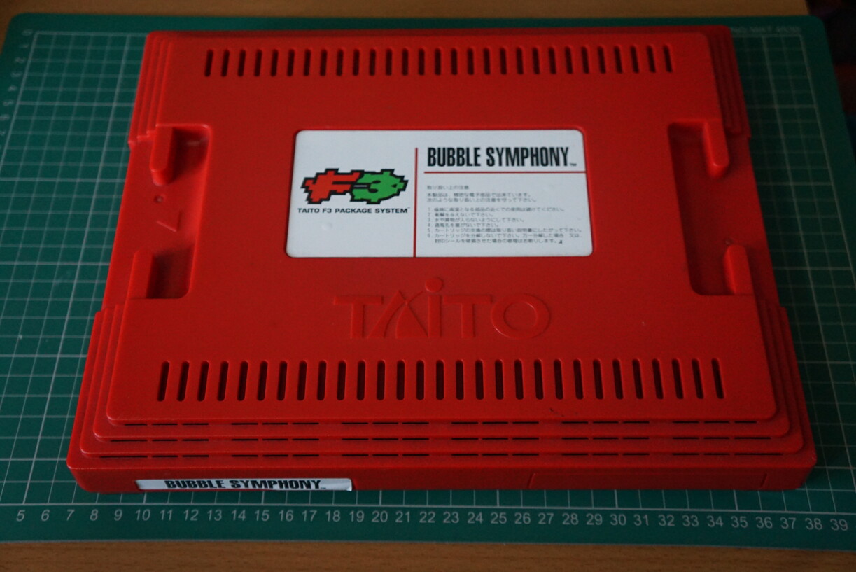
I was originally concerned the game was a bootleg conversion as the seller had taken a photograph of the bottom of the cart which had a serial number of: M20J0122A which would be Puzzle Bobble 3.
So I contacted the seller who sent back a photograph with the correct M20J0104A serial for Bubble Symphony and even opened up the F3 cartridge on request to confirm it was legitimate.
With that I purchased the game and a couple of days later I had it in my hands:
However, due to my hectic work schedule I wasn’t able to test it until today and I was not very pleased to find the game has graphical glitches in the background tiles:


I felt a little deceived by the seller after having a fairly good conversation with him and this issue was never mentioned. Even the listing photographs of the game running appears to be cherry picked for times when these glitches were either very hard to spot or not visible.
But since the price I paid was extremely fair and cheap. I decided I would look into seeing if a repair was viable because well I am a open cart surgeon right?
Let’s look inside!

Nothing looks out of order. No cracked solder joints and no obvious signs of anything bad.
Since the graphical issues were only on the background layers I could immediately narrow my focus down to the three Mask ROM that hold that data:

Using my TTL Logic Probe I tested each of these Mask ROM pins for correct activity using a schematic for the equivalent M27C160 EPROM:

However, everything appeared to be functioning normally.
I knew these were likely the only possible issue, so I then programmed three M27C160 EPROM with the data from the bublbob2.zip that you can find in a MAME ROM set appropriate for these three Mask ROM (d90-08, d90-07 & d90-06).
I then started to carefully piggyback each of these Mask ROM one at a time while the game was powered on to see which Mask ROM would either glitch the affected regions (due to not being able to make proper contact on all pins during the piggy back) or correct the problem.
I quickly found that IC47 (d90-08) was the problematic Mask ROM and so I removed it:

I soldered in a socket and replaced the Mask ROM with the appropriately programmed M27C160 EPROM:

Voila!
The game is now fixed:


Does worry me that some Mask ROM are now starting to die such as this 27 year old one:

6 Likes
Super interesting! I finally got the gear that I need to read/write roms so I’ll be able to start doing some of this myself.
When you piggyback a rom is that what it sounds like? Set the legs of a good rom on top of the legs of a bad one while powered on and see if it fixes the issue?
2 Likes
Yeah, but the problem is getting full contact on all pins is difficult, so more likely to cause more glitching especially when an I/O pin is already giving garbage output on the IC below it.
For any IC with a dead pin especially for stuff like the 74LSxxx IC a piggy back can solve an issue without glitching if you make sure the contacts of the piggy backed IC are tight enough.
But really this method is only good enough for testing purposes and to narrow down your search.
Also got to be super careful not to short pins so a steady hand is required.
2 Likes
Official 360 to XBOX Component Cable Mod:
Last year I ended up being given a couple of Xbox consoles for free that had issues and I’ve spent quite some time figuring out how to mod, refurbish and repair them.
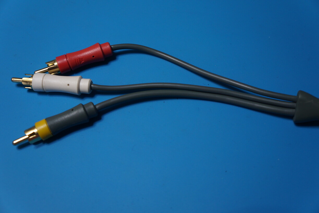
For quite some time I was using a cheap and nasty component cable sourced from China:

These have no shielding in them at all and pick up interference easily and internally the grounds are not even connected…
Unfortunately the Official Xbox Component Cable is hard to come across.
There is another option with the Microsoft Xbox One High Definition AV Pack:

These have become rather expensive to buy and you still have to ensure you purchase high quality shielded component and RCA Audio cables to connect your display to.
However, I discovered that the official 360 Component Cables are very cheap, very high quality and relatively easy to modify to work with an Xbox.
There does however appear to be two variations of this cable one with a ferrite bead and one without:


I fortunately got given one of each type for free by an acquaintance who had no use for them.
Just as a note I found the one without the ferrite bead is a LOT easier to work with.
Let’s start!
First we need an XBOX connector which we can take from a cheap Chinese Component Cable like the one previously pictured (which I used), but you can also take one from an Official XBOX Composite Cable.
To start we cut off the connector from the cable and then throw the cable away, leaving us with:

Using a flat metal pry tool we can pry up the black plastic housing:

We can then wiggle the housing off backwards:

Then using some pliers we can open up the housing that is tightly gripped around the cable:

The two metal pieces then will easily separate and you can pull out the connector:

On these cheap Chinese cables the solder connections have hot glue covering them and I used some needle nose tweezers to carefully remove all of it:

Now we can de-solder the wires from the connector apart from the 2 red wires that loop back onto the connector as they control the cables mode select for the XBOX:

On the larger piece of metal housing you now want to rough up the surface with a file slightly:

and then attach a blob of solder to it, while being very careful not to let the solder go up against the side of the connector as it will not close back up correctly, so make sure to leave a few mm of gap:

Our initial preparation is now complete.
We now need to break open the connectors on the official 360 Component cable, de-solder/remove the small PCB that is used to output digital audio and then de-solder all the wires from the connector.
This will leave you with a bare cable end.
The cable without the ferrite core:

The cable with the ferrite core:

As you can see the shielding is a lot nicer and needs less tidying up on the cable without the ferrite bead and even has slightly thinner ground wires which are easier to solder to the connector, however overall the cable with the ferrite bead has the better shielding but is much more of a pain to work with.
Now going back to the black plastic housing, you will most likely find that the hole is slightly too small to fit over the 360 cable. So using a round file lightly file the cable strain relief:

Until you can easily slide it over the cable:

If you are using the cable with a ferrite bead which you wish to keep and not cut off the cable shorter you will need to cut the cable strain relief off shorter at the first notch as such:

Clean it up either with a file or linishing paper and push it all the way back to the ferrite bead. This will just barely give you enough room to work with:

On both cables you will want to slightly trim the cables back to all the same length and so no wire is exposed and clean up the shielding if it is messy:

The yellow wire is not going to be used so cut this off as far back as you can but make sure to keep its attached ground wire in tact.
With a wire stripper you should strip a couple of mm off the cleaned up wire ends (I found the 18AWG setting to be suitable) and tin these ready to hook them up to the salvaged XBOX connector.
We now need to know the XBOX connector Pin out which I have taken from gamesx:

We only care about the ones below:
01: Audio Right
02: Audio Right Ground
09: Pb (Blue)
10: Pb (Blue) Ground
11: Y (Green)
12: Y (Green) Ground
14: Audio Left
15: Audio Left Ground
21: PR (Red) Ground
22: PR (Red)
If you are using a different type of connector you will need to set the correct mode select pins by wiring:
Pin 6 to Pin 18 and Pin 7 to Pin 19
Thankfully the 360 cables wiring is nicely and appropriately colour coded for us:
White = Audio Left
Red = Audio Right
Pink = Red
Green = Green
Blue = Blue
Black = Ground
Yellow = Composite Video
So now we simply solder all these wires to the appropriate position on the connector:


We will have one single ground wire left over:

Slide the connector partially back into the metal housing and solder this ground to the point you filed earlier:

You can now fully push in the connector into the metal housing and put back on the second part of the metal housing and using your pliers close back together the prongs tightly over the cable.
This is where you will struggle the most on the cable that has a ferrite bead on it as you have virtually no space to work with even after cutting the cable relief shorter:

You can now slide the black plastic housing back over the metal housing to complete your cable:

OPTIONAL:
We are not quite finished yet though!
The 360 cable has a Composite Video RCA connected to it:
Since this can no longer be used, we want to cut it off as close to where the audio RCA wires come off the cable. Using a file clean up around the hole and we can use some epoxy putty to nicely finish this off:

The results:


It is hard to show the improved clarity from a photograph of a CRT but it is much better.
I have a lot more XBOX modding/refurbishment posts to come in the near future!
8 Likes
I did this mod as well, it was relatively simple but I found some good sources for OEM cables for around $30 so I would probably go for those rather than spend the time… and I used an expensive PS2 component cable (they were cheap at the time!) to do the mod soooo oops.
3 Likes
Planning on trying to use a 360 cable to build a better PS2 Component cable for myself as well at some point. I have a load of offiical Sony RF cables lying around with zero use that I could re-purpose the connector from, so hopefully the cable won’t have a too large diameter for it.
2 Likes
Very cool. I’ve only made a couple of cables so far but it’s super satisfying when you hook it up and everything works right.
2 Likes
XBOX S Controller Repair:
When I was doing some repairs for someone local, they said they had a XBOX S Controller that was not working that I could have for free as an extra bonus if I wanted it. So I accepted it!

It is of course dead. On closer inspection we can see the cord is badly damaged close to the strain relief and it looks like the ground connections have become broken:

So first job is to open up the controller. don’t forget that there is a screw hidden under a barcode sticker:

For a quick and easy test, I bent the cable over the controller, pulled out the ground from the damaged part of the cable and soldered that directly to the appropriate connection on the controllers PCB:

The controller now works. So we know this is the only problem!
Now I needed to take note of how the controller is wired up so I flip it back over:

I decided I was going to try to re-use the original cable, strain relief and original connector so I de-soldered the connector from the controller PCB:

Since I did not have enough usable original cable I had to cut it above the ferrite bead and then I also cut it below it to make it easier for me to work on the original connector:

I then pulled off the original cable relief which appears to be bonded to the cable but with some force you can remove it though some of the cables plastic sleeving will end up still stuck inside of the relief and by using some small tweezers and files I managed to clean up after way too much effort:

Now using tweezers again I pulled out all the crimp terminals from the connector and then opened up the crimp around the wire and cut off the wire as close to the crimp as possible:

I then stripped and cleaned up the end of the remaining cable that I was going to re-use, slid the old cable relief back onto it and added heat shrink to finish it up:

Now I simply soldered each of the wires to the original crimp terminals (as it would not be possible to crimp a new contact), re-closed the crimp around the end of the wires and re-inserted them into the connector:

I then soldered this connector back onto the PCB:

I also replaced the analog thumb sticks (360 controllers use the same type):

Then finally I cleaned and re-assembled the controller:

Using the Xbox Controller Tool I double checked everything was working perfectly which it was:

It is a shame I lost the ferrite bead (these help to absorb electronic noise) on the controller end but this will not hinder its ability to function.
3 Likes
Cool, nice work!
Is that Xbox Controller Tool software running natively on an Xbox or something else? I haven’t seen that before.
2 Likes
Yeah, it is a native Xbox application.
But for the life of me I can not seem to find where I got it from originally.
I had intended to link to it in my repair log when I was writing it up.
If you are interested I have uploaded it to my webspace here: Xbox Controller Tool.
Just unzip the archive and ftp it over to you App folder on your Xbox!
It has lots of options and rather useful.
2 Likes
Amazing how quickly something can go from “trash” to brand new!
1 Like
Reminds me what I used to do with N64 Controllers.
I used to find the cables are totally trash, and I ened up replacing the cable with a USB cable with the ends snipped off, one end wired to the N64 PCB the other attached to the controller plug.
1 Like