You should post your pics! If you don’t want to start your own repair thread you could always post in the retro computing thread.
1 Like
I’ll start my own one! You never know I may do another repair.
2 Likes
There you go!
1 Like
Glad it all worked out @matt
Feel free to hijack the thread as much as you like.
Originally I had intended for everyone to use this for repair logs but I later renamed it after it was obvious only I was really using it.
Anyway looking forward to your thread and future repairs!
Good to share the knowledge!
1 Like
Wonder Swan Color Screen Replacement:
I got gifted a couple of Wonder Swan handheld consoles a few years back with not the best of screens.
One of these was a Wonder Swan Color and these don’t have the easiest to see screens since they are not backlit and require fiddling with the contrast wheel and tilting the Wonder Swan at often strange angles to be able to see anything:

Recently Hispeedido (Chinese) developed a replacement IPS screen for only the Wonder Swan Color and I decided to give it a try to make mine playable.
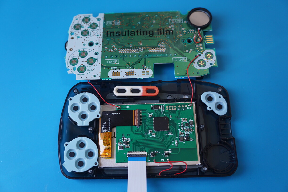
Using a T7 Security Torx bit I disassembled my Wonder Swan Color:

Using some flat nosed tweezers carefully release the flex cable for the original screen:

Using a plastic spudger I also carefully pried up the original LCD and plastic lens which left me with a totally disassembled Wonder Swan Color:

New IPS LCD on the left compared to the original screen on the right:

And the original plastic lens on the right compared to the replacement one on the left:

Installation is fairly easy just requiring you to remove the white foam spacers,applying some isolation tape, applying some double sided tape and soldering two wires from the battery terminals to provide power and ground to the new screen:
NOTE:
The flex cable on these new screens appear to be very fragile so be very careful with it!
I had to get a replacement screen sent out to me as the first one I received was dodgy…
There are two “touch” sensors that adjust the brightness (TP1) and colour palette for black and white only titles (TP2). I found these to be very temperamental and often ended up palette cycling by accident (or even seemingly at random) but it appears to remember whatever you set it to on powering off the unit.
So after setting the brightness to my liking and making sure it was using the default colour palette I removed both of these sensors:

Another problem I found was since my Wonder Swan Color has a clear housing I could notice light bleeding through on the left side of the handheld:
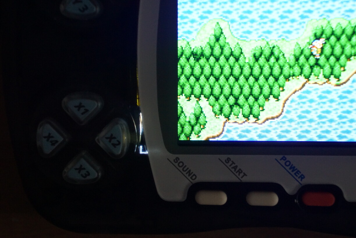
So to help counter this I added some black electrical tape to that side of the screen:

It doesn’t 100% cure the back-light bleeding through the clear case but it is far less noticeable:

Comparison shots:
Final Fantasy 2 at Title on Original Screen:

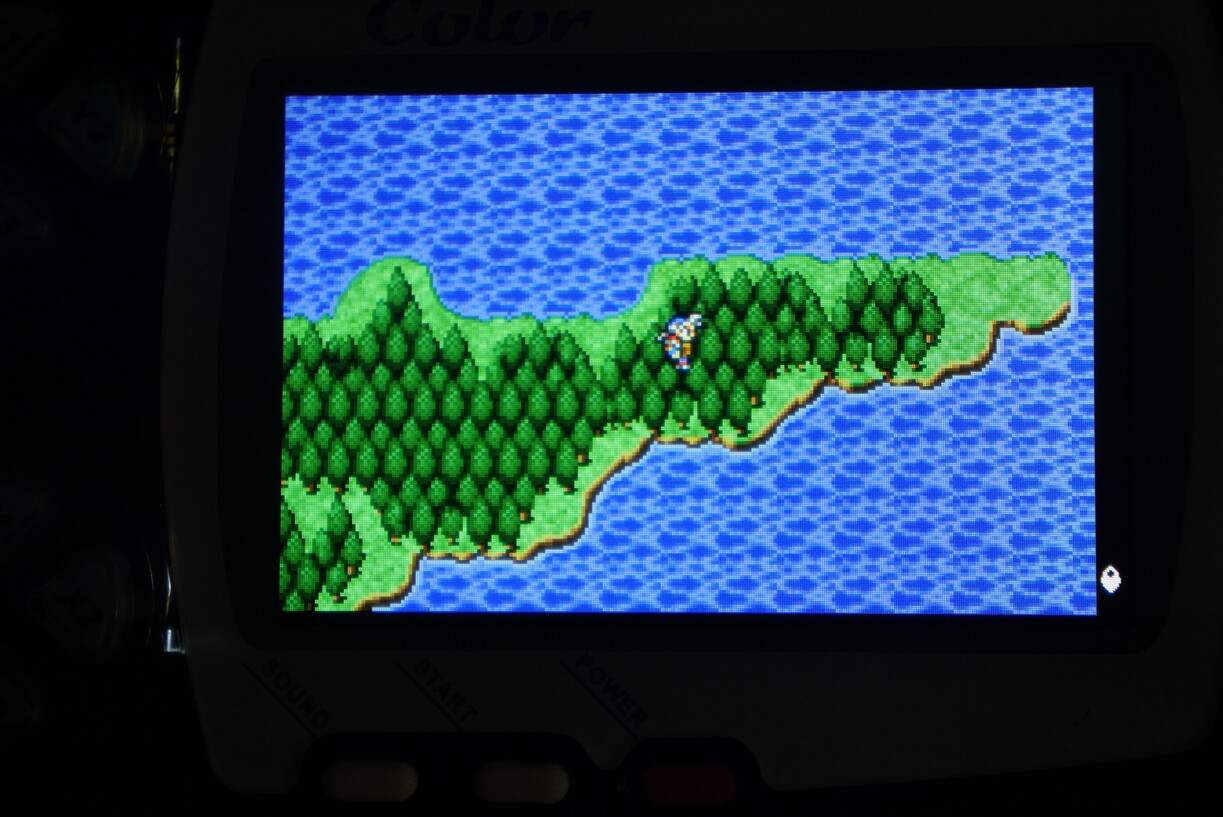
Final Fantasy 2 at Title on New IPS Screen:

Final Fantasy 2 on World Map on Original Screen:

Final Fantasy 2 on World Map on New IPS Screen:
New IPS Screen with Black & White only Title:

However, it is not perfect. There is the temperamental sensor issue I mentioned previously for one.
Then battery drain appears to be much worse in comparison to using an original screen and you may now only get a couple of hours use out of the Wonder Swan Color from one AA battery.
I am also noticing when the screen flashes pure white that there appears to be an occasional v-sync tear in the middle of the screen.
The good is that this is easily reversible back to an original screen if you ever wished and It is really nice being able to actually comfortably see the screen now.
5 Likes
Looks awesome! Great job. Good trick using the electrical tape.
1 Like
Ohh I’m so glad they replaced it, I was wondering about this!
It looks amazing too, great work yet again Suteneko!
2 Likes
I was really set to buy one of these until I saw a) the 2-3 hour battery life and b) when the f did wonderswan colors get expensive?
1 Like
Yeah the battery life thing is really off-putting for me as well.
I was kind of shocked after just shy of 2 hours of testing that the battery warning light started to slowly flicker on, so 3 hours tops seems to be the best it can last with these new screens.
I think it is probably more cost effective to just go all out and buy a Wonder Swan Crystal instead unless you can pick up a cheap Wonder Swan Color.
1 Like
I was eyeing up some a few months ago and yeah it’s crazy how much they’ve shot up in price. Such a cool looking handheld.
this reminds me I still need to source a replacement CD-Rom drive for my Japanese PS1
1 Like
SEGA NAOMI MAPLE Controller Adapter for Dreamcast Controller/VMU:
I’ve been wanting to make myself some maple adapters for my NAOMI and even had everything required for several years now, but for one reason or another I kept putting off the work.
Required parts:
Dreamcast Extension Cables x02
H10P-SHF-AA x01 (JST, NH Female Connector Housing, 2.5mm Pitch, 10 Way, 1 Row)
H11P-SHF-AA x01 (JST, NH Female Connector Housing, 2.5mm Pitch, 11 Way, 1 Row)
SHF-001T-0.8BS x12 (JST, NH, SM Female Crimp Terminal Contact)
This is the type of Dreamcast extension cable I am using:

First we have to break open the male plug

Then I cut off the wires from the male connector and remove the cable relief and discard:
Then simply strip the all the wires, add heat shrink to the main cable and crimp the JST NH female terminals onto the 6 wires of both cables like so:

As usual for me I add some solder to ensure the connection is good.
Then using this guide I found online we insert everything into the correct connector:

You do not have to connect the 6th wire which is a cable ground, however I connect it to one of the additional grounds located on CN6 at pin 5 and CN7 at pin 9.
The results:

Close up of the player one Maple adapter:

Inserted into the SEGA NAOMI:

Not every NAOMI title supports Dreamcast VMU/Controllers and some of the titles that do, may require you to go into the game settings and turn the option “C-PANEL USE” ON.

Now my Dreamcast controllers function on my NAOMI:

Ideally I need to find a good place on my control panel to cut and mount the DC controller connector, but haven’t decided on anything yet.
The best thing about this is that you can use a Dreamcast Keyboard to play typing of the Dead and some VMU saves from Dreamcast ports of the arcade titles can be used.
3 Likes
Sharp work as usual!
1 Like
I haven’t wrote one of these in a while and have a back log of repair logs to add at some time but for now let’s start with my most recent project to get back into things and maybe try to work backwards a little before I forget everything…
So
SEGA System 16B E-Swat ROM Board Repair:
I had been watching an auction for an over priced E-Swat ROM board for a while:

It was the discarded left overs from yet another Dark Soft Multi where only the System 16B Motherboard was required. It was listed as working perfectly but you can clearly see a capacitor is half ripped off and the CPU that held the encryption key for the PROG data was missing.
I contacted the seller, but he was adamant it works perfectly fine and found out he had just thrown away the old CPU when he replaced it with a regular 68000 for the multi to work.
So I left it some more until eventually after many months it got discounted down to £25 and I decided that was low enough of an amount for me to take it on.

As I had already noticed one of the capacitors was just barely hanging onto the board:

So I removed it and cleaned up the via’s of the old legs:

Then replaced the 470µF 16v capacitor with a spare (and slightly taller) 470µF 25v capacitor I had to hand:

I also noticed that the custom SEGA 315-5248 IC on the reverse of the PCB has flux remnants:

It looks like a few IC legs in one corner were re-soldered back down at some point in the past.
I double checked continuity (which was good) and just cleaned up the flux.
I then removed the PROG EPROM at IC positions IC1 and IC2 and dumped their data using my Universal Programmer.

Once dumped I compared their CRC and discovered they are identical to the E-Swat SET 2 JAPAN (eswatj) ROM in mame so I just needed to take the decrypted PROG ROM files from (eswatjd) and program them to two 27C2001 EPROM.
Unfortunately I was having problems with the ST M27C2001 I had spare having stuck bits so I ended up erasing the original NEC D27C2001 and re-programming them instead and placed them back in their appropriate IC sockets:

Then using some IPA I cleaned off the marker pen:

Then I cleanly removed the “O.K” sticker label and finally replaced my Shinobi ROM Board with this E-Swat ROM board:

It lives again:


7 Likes
Awesome write up! Super informative.
2 Likes
Awesome job, thanks for sharing
2 Likes
Gameboy Color No Power Repair:
Recently my brother found this Gameboy Color discarded in a field:

It is missing its battery cover and wasn’t powering on so he brought it over for me to look at and I could see that one of the battery contacts was badly corroded:

So using a Fibreglass abrasive cleaning pencil I cleaned the contact as best as I could and inserted some new batteries:

A surprisingly easy fix:

5 Likes
Gigabyte GA-8S655FX Socket 478 Motherboard Refurbishment:
I have been looking out for some old Socket 478 Motherboards to build a Windows '98 PC around and stumbled across a cheap local PC that contained this motherboard along with some other odds and ends that were interesting to me.
This Gigabyte motherboard boots and operates fine, however after looking closely at it, I could see that three capacitors were badly bulging and it is well known that a capacitor plague was haunting a lot of motherboards from this era (1999-2003):

These were promptly removed:

and tested:

Very bad ESR as expected, but on closer inspection you can also see that not only had they bulged and were leaking fluid from the top they had also ruptured at the bottom of the capacitor:

All the bad capacitors were Chemicon KZG (3300µF 6.3v 105°C) which is a known BAD CAP.
I checked the motherboard for any other KZG type capacitors to remove but did not find any.
For my peace of mind I then in circuit tested the ESR of the other capacitors and found they were all in good standing and the ESR was mostly reading at a very good 0.2Ω reading.
I however did not have three new 3300µF 6.3v 105°C capacitors at hand, but I do keep a tub of capacitors I have removed from junk boards (or from complete recaps) that test good for ESR and capacity:

It is especially good to save the large high voltage capacitor from junk devices as they are expensive to replace and rarely go bad.
In here I found three suitable replacement Rubycon MBZ capacitors.
These I re-tested before soldering them into this motherboard:

Lastly the original CR2032 battery was dead as expected so that got replaced with a new one.
This motherboard is now good and safe to go again:

5 Likes
Neo Geo MVS 2 Slot (MV-2F) Refurbishment:
Back in February 2018 I bought a untested and possibly faulty Neo Geo MVS MV-2F that the previous user had tried to consolise but never got around to finishing the job.
Unfortunately the original ebay listing is no longer viewable and for some reason I don’t appear to have taken any other photographs of the unit untouched at arrival.
First Job I had to do was remove all the wires soldered directly to the Neo Geo:

The bad news was that the JAMMA edge contact pad “P” which is Video Sync had ripped off the PCB but thankfully the trace was still intact.
So using some high temperature epoxy (DO NOT use super glue as it can be conductive and when you apply heat it will give off toxic fumes, use something like Circuit Works CW2500) I bonded the JAMMA pad back down onto the PCB:

Using De-Soldering Braid I then removed as much solder as possible from all the JAMMA pads:

The original battery was leaking so it was removed:

I decided to replace it with a 3.6V NiMH 80mAh Rechargeable Battery:

Since this had an extra mounting leg on the positive side I had to cut one off to solder it flush to the PCB:

The original capacitors for the most part didn’t look too bad but I decided to fully recap it:

The MV-2F comes already fitted with a socket for the BIOS:

So I removed this and replaced it with a Uni-Bios I had programmed to a 27C1024 EPROM:
Using the Uni-Bios allows you to be able to use (then cheap) PCMCIA SRAM Memory Cards instead of having to try to find a expensive official Neo Geo Memory card.
The benefit being the PCMCIA SRAM Memory Cards tend to have an easy access user replaceable battery and a capacitor that prevents data loss when you change it and much larger capacity:

However, you must only access it via the Uni-Bios Memory Card Manager (hold A,B,C&D at boot up):

Another perk of the Uni-Bios is the ability to also be able to store High Scores:

The metal housing for this Neo Geo had become quite rusty:

So I applied some Hammerite Rust Removal Gel:

and after several re-applications and scrubbing we have a rust free housing

This I then applied a white undercoat to the top of the housing:

Left to dry and repeated to the rear:

This was then sprayed black and a gold SNK vinyl was applied giving me the finished product:

8 Likes
Neo Geo MVS 2 Slot (MV-2F) Graphic Corruption Repair:
Recently while I was testing my new JAMMA setup I found that I was unable to get this 2 Slot MVS to sync with my arcade monitor:

I discovered that the delicate trace for the Video Sync had broke at some point in storage:

So I had to run a small bodge wire to fix the issue:

But then… Suddenly I started getting graphical issues urgh:

I replaced the Uni-Bios with a freshly created Neo Diagnostics BIOS to help diagnose the system:

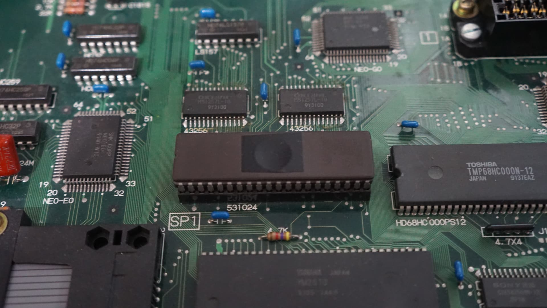
It appears I am getting the error message: VRAM ADDRESS (A8-A10/A8-A14)
So it looks like the VIDEO RAM as gone bad and from the low address that failed it looks like it was the slow ram which is a pair of SONY CXK58256MM-12 RAM:

While I did locate some identical NOS RAM in China which I ordered, I didn’t want to wait and thus looked to see if I could find a local UK seller with stock of a 5volt 256kbit SRAM JEDEC pin compatible, 32K x 8bit, 120ns or faster RAM in a 28 pin SOIC package that I could use and found some NEC UPD43256BGU-70LL RAM that I could use and got it delivered the next day:

I use a hot air station and plenty of flux to remove the original video ram:

Then drag soldered in the replacements:

Success all Diagnostic tests now pass:

I then removed the Neo Diagnostics BIOS and re-inserted the Uni-Bios.
Everything is now back to working as intended:

9 Likes