Honey I've Shrunk the PVM - A CRT Maintenance Log

Replacing all those capacitors…

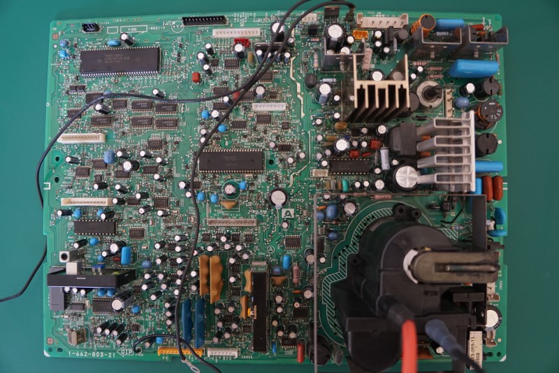
To help make replacing all the capacitors easier I marked all the old ones with various colour marker pens and made my own colour code legend to work from.

In doing so I found that I had 1 too many 25v 47µF capacitors installed (I was marking them purple) according to the capacitor map/list I had compiled from the service manual. So I double checked and found that location C1382 should have a 100µF 10v capacitor installed. At some point in the past this capacitor must have been replaced and it does appear that this may have been done due to a service update, however I can not 100% confirm this and using either 100µf or 47µf seems to make no perceivable difference.

Also you can see a few polymer capacitors had been installed but it is perfectly fine to replace them with electrolytic capacitors.

It really does pay to have a service manual at hand.

I had spent a lot of time doing this tedious work and was getting very tired.

Can you spot my mistake?
Click through to the larger image if you can not spot it… :wink:

On most good PCB all capacitors will generally only have the negative poles universally facing in two directions. This makes spotting a mistakes at a glance a lot easier. But always double check everything.

192/192 - Recapping completed:

Flyback re-installed and ground cable re-connected on the A “motherboard” PCB:

G “PSU” PCB re-inserted into its plastic housing ready to have its ground and heat shield re-attached:

Q “I/O” PCB needed re-attaching to its I/O connectors and soldered back together.

The remote port is quite difficult to get its small pins lined back up with the PCB and I was having trouble with getting the pins 9,10,11,12 to stop bridging with each other which was a bit frustrating but ultimately pointless as after checking its pin-out found they are all ground pins so having them bridged makes no difference what-so-ever!

The C “Neck” PCB also had its 3 capacitors replaced but I forgot to take another photograph of it!

And here is a small plastic tub full of the removed capacitors:

Re-assembling:

First I put the motherboard back in its plastic housing and screwed it back down to it. Then I slid it back into the PVM tray housing and started to re-connect everything that is at the “screen” front of the PVM as getting access to them later would be difficult.

While there is an awful lot of cables to re-attach during this assembly, all the connectors are unique so you really can not go wrong, but I had previously left them all hanging close to their original locations anyway.

Next I re-attached the PSU and the re-connected its cabling again from the “screen” front of the PVM before sliding the motherboard fully back into the PVM.

I then re-attached the Neckboard to the CRT and the I/O board back in its location to the rear of the motherboard sliding tray housing. Followed by connecting the focus adjustment pots back to the I/O board and then screwing back in the ground plates and all the ground wires, along with connecting any remaining wiring.

Finally I re-attached the anode cap to the CRT and started praying will this still work?

To be continued tomorrow, I need sleep now and still a fair bit to write up!

3 Likes

Just wanted to say I love following along with this.

Amazing dedication. Thanks for sharing in such an in-depth manner!

The anticipation!

Powering back up for the first time:

Now the PVM is back together it was time to check if it still works. So just in case there was some problem or I needed to do some calibration I left the rear casing off, found out an extension cable, hooked back up the power cord and very nervously pressed the power button:

IT LIVES AGAIN! Phew!

Before I moved it back to my main setup so I can test its inputs I returned all the settings back to their factory default. If the PVM’s original Factory Setting has not been re-written you can just use the built in factory reset to achieve this but this is often not the case and instead you can find a list of the default settings for each adjustment in the service manual and then save this by using a Factory Setting to re-write the info. Check out section 3 of the service manual I uploaded/linked to in my first post for in depth details on how to do this.

Testing Inputs:

With the PVM now moved back into my setup and reconnected back up to my Extron Crosspoint I proceed to test RGB, Component, Svideo and audio inputs and everything is good.

I make some minor alignment adjustments to find my “sweet spot” between all the common systems I use, which will never be perfect for everything but concentrate mainly on Megadrive, CPS1&2, MVS and getting 576i aligned as best as possible as they are my most used input devices.

I was expecting to have to adjust the focus pots but didn’t seem necessary at all, so I now put the rear casing back on and left the PVM on over night to burn in.

What was my total cost?

My total cost ran to just shy of £70GBP which isn’t too far from my original purchase price point of this PVM itself. I could have possibly gotten the price down by ordering capacitors from china and using lower grade capacitors but my thinking in the end was more along lines of if I’m doing this I am going to do it correctly and go all out.

Instead of cheaping out I upgraded every capacitor to 105c and high durability capacitors. I also opted for quality Rubycon capacitors whenever possible and for Panasonic and Nichicon branded capacitors for anything else.

Time wise I spent roughly 20 hours working on it over 3 of my days off from work.

Was it worth all the effort and extra cost?

Now this is something that is hard to answer.

Immediately I noticed that my PVM is now a lot quieter than before and the old high pitched squeal it used to have is gone and replaced with a much gentler hum.

The screen is also much brighter now with the colours popping more so than before. I used to be able to notice a stark difference between this PVM-20M4A and my RGB only PVM-1450QM. Where the the 14" PVM was much brighter and I had to ramp up the brightness dial on my PVM-20M4A right up and it would still not be as good colour and brightness wise.

Now if anything the PVM-20M4A edges it out:

The geometry does appear to have improved, but that is more subtle and difficult to discern. Especially by how much or little relatively the re-capping has made a difference. Some adjustments no longer needed to be made and others didn’t need to be made as much as previously. Just it is very hard to quantify precisely.

I’m am happy with the results and the improvement in my soldering skills and PVM knowledge gained through the experience have been noticeable. So… Yes? :wink:

I will post a follow up reply another time to go over some concerns I have and where I recommend other people to look at first when thinking about doing a recap or repair.

7 Likes

Amazing, thanks for posting all of this! I love reading through stuff like this and fixing/refurbishing things.

This is huge for me. I have a few CRTs, and one squeals loudly and the others just hum softly… so softly that one can easily forget to turn them off when no image is displayed. The squeal can be grating after a while.

Anyways, congrats to you. Sounds like a highly successful project in my humble opinion. And it made for one of my favorite threads on the site so far.

Just noticed my CRT Surgeon title! :sweat_smile:

It has been a while coming as I’ve had to get some image editing done and no longer have easy access to the PCB’s for reference, but here is my PVM-20M4x follow up notes:

Capacitor Replacement Notes:

A PCB: Motherboard:

Below you can find an image I’ve made to highlight where the worst offending bad capacitors I found are located or believe are critical and should be replaced (red boxes) and I have highlighted inside the orange box locations where I would recommend you replace all the capacitors. I have also highlighted in purple boxes a couple of concerns that we will get to later.

C PCB: NECK BOARD:

While I found no issues with the capacitors here. There are only 3 of them and they are critical to the health of your CRT so REPLACE them!

G PCB: POWER SUPPLY:

Again I have highlighted in red boxes where the worst capacitors are located and these should be REPLACED with 105c and the highest durability capacitors you can find. The smaller capacitors left around the fringes of the PCB could possibly be left alone if you want to save a few pennies.

Q PCB: I/O BOARD:

I do NOT recommend you spend the time and effort to recap the I/O PCB. I did not find any issues in that area and it is a lot of effort to gain access to it due to having to desolder all the connectors from it. I would instead check it as best as you can to see if any caps are leaking and if they are not leave it alone.

CONCERNS:

1 - Hot Area!

When I originally opened up my PVM I found a few High Voltage Switching Transistors without any heat sinks on them had bent over and were directing their generated heat down towards the A PCB.

All but one of them are in locations where it doesn’t really matter BUT the 2SC4686A transistor at Q526 is obviously a cause for serious concern as when it eventually over time tilts due to the heat generated it starts to direct its heat on top of the capacitor at C1501 and the two MC14538B Monostable Multivibrators at locations IC502 and IC503.

I’ve zoomed into the offending area below:

You can see that both of the Monostable Multivibrators have some heat damage to the top of their packages. Thankfully the heat had not damaged the IC’s enough to affect them yet and replacements can be easily and cheaply sourced, though you would ideally need a hot air rework station to replace them which I don’t have at present.

The heat from the transistor is probably what caused the C1501 capacitor to start leaking and the combination of this heat and leakage from the capacitor has caused some “mottling” to the rear of the PCB under this area.

It might be worthwhile to try to figure out a way to add a heatsink to this offending transistor. For now I have straightened up all the high voltage transistors and would recommend people keep an eye on them.

2 - Thermal Paste Renewal:

While I did not do this myself yet due to not having any thermal paste at hand, it is probably a good idea to replace the thermal paste for everything that is attached to a heat sink as by now it is pretty much all dried up already.

3 - NEC Sync IC Concerns:

The NEC PC1377C IC controls the SYNC on this PVM. It is also located in an area that generates a fair amount of heat which is of concern. If you are having sync and/or rolling image issues replacing this IC should fix the problem. I managed to find some new old stock of this NEC IC on ebay for about £2.50GBP per piece but who knows how available it will be in the future so it might be worth investing in a few for spares.

4 - OSD Issues:

I had not run into this issue before. However after the re-cap and performing a factory default setting reset, I started having issues with the OSD on my Panasonic DMR-EZ48V with the upper part of the OSD getting cut off at the top to the screen even when I lowered the vertical position to display way past the over-scan area.

It took me a while to figure out what was going on, but it appears that some devices use vertical blanking to position their OSD and if you get this same issue all you need to do is adjust the appropriate V Blanking setting to align the OSD correctly as pictured below:

It’s not over yet… Second CRT project incoming!

2 Likes

Respect due.

That was some Necro-Bump.

Totally forgot to write up the second CRT related project. I should get around to that sometime.

Sadly the above PVM-20M4A is faulty after it was accidentally fed a 1080i 50hz signal that was meant for another monitor. It now refuses to display any PAL or 50hz video no matter the input. Fortunately it still can display NTSC 60hz (and PAL60 over RGB) but I had to re-adjust the calibration settings towards some of the maximum values to get the screen re-aligned for NTSC.

I’ve been trying to diagnose it for several weeks now and even socketed some of the IC’s to no luck. I highly suspect that the NEC PD78013YCW 8bit Microprocessor got damaged and it is unlikely I’ll be able to find a replacement for it short of finding a donor monitor with the same IC in it.

Guessing it will end up having to be a dedicated Arcade/NTSC gaming monitor.

I did my first PVM cap kit yesterday and it turned out great! I had a spare 1954q sitting in the garage for a year or so and just never got around to fixing it. It had really bad jagged noise in the sides and you couldnt even adjust the horizontal width. I ordered a kit from Savon-pat on eBay and swapped them out,job only took a couple hours (finding the caps took the most time!).

Here is a before video

And After

4 Likes

Thanks for the diameter measurements.

I needed to replace C584 to get rid of the lines at the top of the screen on my 20M4U and decided I to replace every capacitor, hoping to regain some brightness. The geometry was already good and didn’t change much, if at all, after re-capacitation (but needed to be re-calibrated through the service menu).

The default color temp settings D65 and D93 now look great. I don’t need to use custom settings anymore. Brightness is better but still needs to be turned up for proper black levels. It’s still not as bright as my other monitors/TVs but looks much better after re-capacitation.

Some notes:

-Total cost for me including tax and shipping from digikey was $97. That’s a lot of money for capacitors but I bought mostly Nichicon and Panasonic with higher temperature and lifespan ratings.

-Getting access to and replacing capacitors on the I/O board is indeed a huge hassle and not worth the time. I did it anyway.

-Despite being very careful and using proper equipment, I lifted a few pads and broke some traces. I haven’t worked on such fragile PCBs before. Repairing broken traces and pads really made things slow and unpleasant.

-Regarding C1382: most likely 47uF 25v is the correct value. The schematic in the service manual around C1382 differs slightly from my board so I stuck with 47uF 25v. It’s likely that this part of the circuit was revised for later productions of the monitor after the service manual was written. Also, the service manual is missing a few capacitors on the parts list so that is another indication that the manual is outdated. And of course the manual also lists the wrong value for C584.

-The “INCORRECT METAL FILM CAPACITOR INSTALLED” that you have indicated are polymer capacitors. Most likely those are the original capacitors from the factory and are the correct parts but can be replaced with liquid electrolytics (as you have done).

-You may have missed capacitor C813 on the “S” board (tiny board attached to the main board)

-“left the PVM on over night to burn in” What is this for? I have only heard of doing this for plasma TVs.

1 Like

Glad you found the measurement useful!

Breaking traces is definitely always a worry, having temperature control on your soldering iron is a must. I have gotten pretty good at desoldering with just braid and a solder sucker and have not damaged any traces on my PVM even when I was removing some of the larger through hole IC’s so they could be socketed for testing purposes. Same can not be said for a recent NeoGeo MVS BIOS desoldering where I accidentally ripped up a trace even though I was being super careful but a bit of Kyna wire fixed that.

Consumer CRT sets are a lot easier to work on as they tend to only use a single layer PCB from what I have seen so far.

Thanks for the confirmation. I should update the above posts to reflect this.

I believe this might be the case as C584 was already changed as per a service bulletin. I did try to find out more information regarding Sony service manual updates but didn’t have any success and trying to talk to Sony directly was pointless as they won’t assist with any hardware that they are not currently selling. I will probably replace C1382 with a 47uf 25v next time I open it up.

I doubt it was necessary for me to leave it on over night. Just wanted to let it warm back up fully before doing any calibration and to ensure the new capacitors had plenty of time to normalize.

Sadly my PVM20M4A is still out of commission. I managed to get it to display PAL video again but I had to adjust V Blanking almost to the highest limit of adjustment which broke the 16:9 mode.

I also had to adjust the focus, TVL and convergence as it was a fair bit off. But my best adjustment leaves the RGB convergence slightly out towards the top right side of the screen. Might be able to iron that issue out with convergence strips and further fine adjustments to the convergence rings (which I have not touched yet).

V Blanking worries me the most. I need to find a way to bring that setting back down.
Also need to look at replacing a few surface mount IC’s that are showing visible signs of wear.

I’m surprised you desoldered nearly 200 capacitors without a powered desoldering tool. It’s already a very long and tedious process with a powered tool

1 Like

Use the following 2 capacitors as replacements for the high ripple caps found on board A.

c572 4.7uF 160v UCC KHA -> EKXE401ELL4R7MJ16S
c584 1uF 160v UCC KXB -> EKXE401ELL1R0MHB5D

KHA and KXB are superseded by KXG series but KXG starts as 6.8uF. KXE appears to be a new series with the capacity that we need.

2 Likes

Hey does anyone have a digikey cart for a PVM-20L2?

I’m looking to do a full recap of my unit as it has some slight horizontal smearing but also for longevity.

Anyone have experience using these tweezer-like soldering irons? After watching videos of people removing surface mount capacitors, I wondered if there was such a tool, and found that there is. Now I can’t help but wonder why I don’t see such tools being used by modders whom I would consider to be quite knowledge.

1 Like

never seen it, but they look really useful. maybe because the tips are too bulky?

For me at least it is very hard to justify the cost of them for the amount of use they would get.

They can be had for $25, or $300 if you want Hakko equipment. Have you used them? If so, what is your experience? I’m curious if they are any good for electrolytic caps.

1 Like