Honey I've Shrunk the PVM - A CRT Maintenance Log

I started posting about this in the Discord but thought it was better to continue on the forums.

My PVM20M4A has needed some maintenance for a while now. I was aware a couple of capacitors close to the flyback transformer are in bad shape. It also has a few minor geometry issues which I had hidden in the over-scan area and very occasionally the colour hue would change slightly but a power cycle always corrected in the rare times it has happened.

Since I had been away traveling in Japan for a month, the 20" has had plenty of time to discharge as it was left unplugged and it feels like the perfect time to give this CRT a good cleaning and a recap.

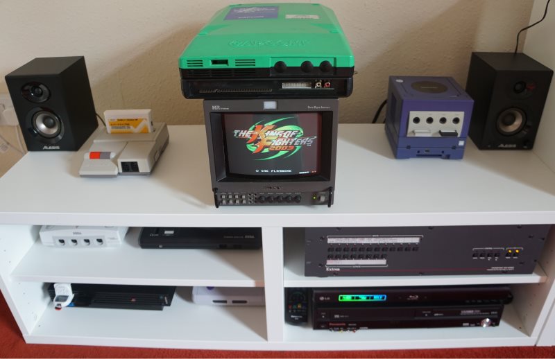
In the mean time my 9" BVM (that has been sitting in my storage cupboard for over a year) is replacing it in my setup has my 14" PVM is RGB/Composite only.

WARNING:

I am just an amateur hobbyist who has slowly self taught himself some basic skills required for modding consoles and maintenance. I am in no way trained or certified, have large gaps in my knowledge and this will be the biggest project I have worked on so far.

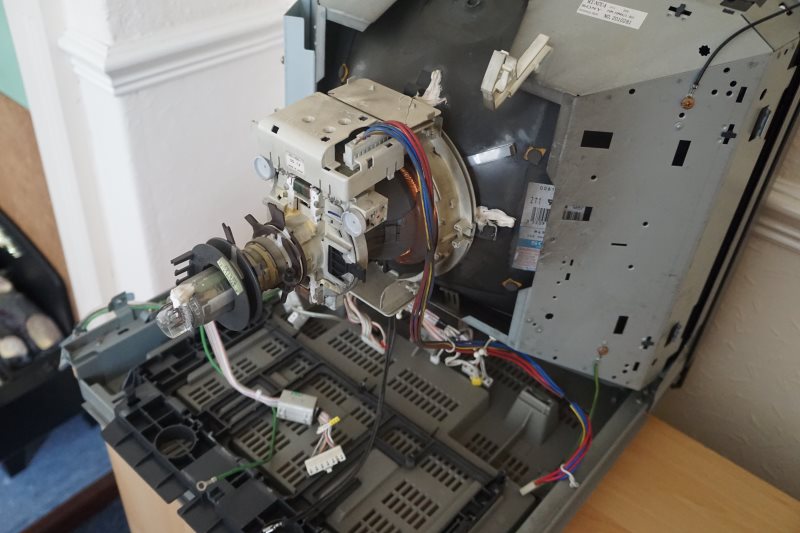
So here she is:

Unfortunately I don’t have decent pictures of the issues prior to starting work on this, so this is a several years old photograph of the best settings I was able to produce using a grid test will have to suffice. As you may or not be able to see I had to crop out a few lines at the top of the screen into the overscan area to hide a flagging issue in the upper top right area and their are some issues in both lower corners of the screens geometry.

Just a quick note regarding the “A” region:

The PVM20M4A is a southern hemisphere CRT (from Australia) that somehow ended up being used in the UK (northern hemisphere). While this has not appeared to cause any real issues, it does however hate being put in close proximity to my other broadcast monitors (correct hemisphere) and starts to display the picture with some “wobbling” until I put some distance between them while powered on.

TOOLS USED:

  1. Phillips Screwdriver
  2. Hakko FX-888D Soldering Station
  3. Hakko Solder Sucker
  4. MG Chemicals Solder (0.032" Diam 22 Gauge 2.2% Flux “No Clean” Sn60/pb40)
  5. Desoldering Braid (1.5mm Width)
  6. Liquid Flux
  7. 99% Isopropyl Alcohol
  8. Cotton Buds
  9. Long Nose Pliers
  10. Mitutoyo Vernier Caliper
  11. Fluke 15B+ Digital Multimeter

LINKS:
Sony PVM 20M2x User Manual
Sony PVM 20M2x Service Manual

TO BE CONTINUED:
4 Likes

MAINTENANCE LOG:

  • Removing the PSU

The power supply board was the first thing I removed.

You can safely remove the two screws holding it to the CRT housing.
It will not fall down as you need to slide its plastic housing upwards to unclip it.

You need then to unplug 2 connectors at the top of the board (there is also a third empty connector there) and unscrew the earth wire.

There is then a connector to disconnect at the lower left (front) of the PSU.

Now you have to slide the unit upwards to unlatch it to get access to the last 2 wires you need to disconnect (again there is a third unused connector here).

Finally I unlatched any wires that were still in the cable management clips and removed the PSU completely from the PVM.

  • Removing the Anode Cap

I have seen plenty of videos of people shoving a screwdriver under the Anode Cap to cause a short to ground accompanied by a loud spark. I have also read lots of conflicting safety practices regarding safety and the “correct” method of doing so.

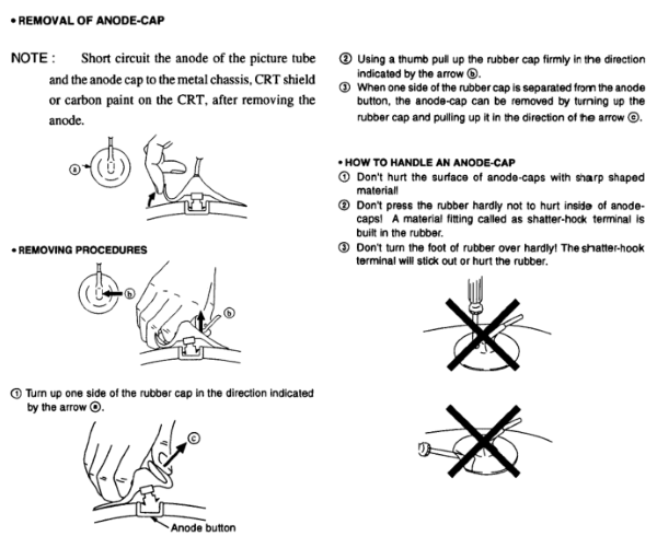
I instead chose to let it discharge unplugged over a month of time and followed the instructions provided in the official service manual (link at bottom my first post) for the monitor:

Everything went well and short circuiting of the node cap to the metal chassis caused no pop or sparks.

  • Removing the I/O Board

While I did not carry this out in this order for future reference to make things easier; unscrew two of the grounds (pictured below) from the grounding plate BEFORE disconnecting it from the I/O Board.

You then also need to remove the Focus Adjustment from the I/O Board:

Then just disconnect the two cables at the Motherboard and then lift the I/O upwards to painlessly separate it.

  • Removing the Motherboard

Very gently pull the Neck Board away from the CRT. There is a dab of white epoxy holding it in place so you may also need to lightly rock it to free it.

At position CN703 is another black Earth wire that is on a quick release crimp. I could not remove this by hand and had to use some long nose pliers. We do not need to disconnect anything else from the Neck Board just leave everything else connected to the flyback transformer and motherboard.

Now we can slide the black housing that the motherboard is bolted to by 3 screws slightly back, just enough so we can easily get access to and disconnect the 7 cables connected at the CRT front of the board.

Finally we can fully slide the motherboard housing out towards the back taking precautions not to let the loose Anode Cap touch anything or damage the Focus Adjustment pots and Neck board.

  • And we now have a stripped down PVM!

  • BUT… I/O Board nuisance

You can not actually access the I/O PCB or replace any of the capacitors on it without having to desolder all of the I/O connectors from it with the exception of a single S-video Output (remove 2 screws) and you must also desolder the I/O plate ground tabs from the PCB which require you to also twist them straight (I used my long nose pliers again) after desoldering to be able to push them out of the PCB.

I really did not want to have to do this but 30 minutes later I’m done:

3 Likes

PVM-20M4A ELECTROLYTIC CAPACITOR LIST:

All measurements are capacitor diameter measured with a vernier caliper

  • Motherboard “A” PCB:

0.47uf - 50v (04) [5mm]
1uf - 50v (09) [5mm]
1uf - 160v (01) [8mm] [105C Required]
2.2uf - 50v (03) [5mm]
3.3uf - 50v (01) [5mm]
4.7uf - 50v (11) [5mm]
4.7uf - 160v (01) [6mm] [105C Required]
4.7uf - 160v (01) [8mm] [105C Required]
4.7uf - 160v (01) [10mm] [105C Required]
4.7uf - 250v (01) [8mm] [105C Required]
10uf - 50v (23) [5mm]
22uf - 50v (02) [5mm]
22uf - 250v (01) [10mm]
47uf - 16v (03) [5mm]
47uf - 25v (43) [5mm]
47uf - 50v (01) [6.5mm]
100uf - 10v (03) [5mm]
100uf - 25v (04) [6mm]
100uf - 50v (02) [8mm] [105C Required]
220uf - 16v (01) [6.5mm]
220uf - 25v (04) [8mm]
220uf - 160v (01) [18mm] [105C Required]
330uf - 16v (03) [8.3mm]
330uf - 16v (01) [12mm] [Using 8.3mm is fine!]
470uf - 10v (05) [6.5mm]
470uf - 50v (01) [10mm]
470uf - 100v (01) [16mm] [105C Required]
1000uf - 16v (03) [10mm]
1000uf - 25v (01) [10mm]
2200uf - 16v (02) [12.5mm]

  • NeckBoard “C” PCB:

10uf - 250v (01) [10mm]
22uf - 250v (01) [10mm]
100uf - 16v (01) [5mm]

  • Power Supply “G” PCB:

10uf - 50v (05) [5mm] [105C Required]
47uf - 35v (01) [5mm] [105C Required]
47uf - 50v (01) [6.3mm] [105C Required]
47uf - 160v (01) [12.5mm] [105C Required]
100uf - 50v (01) [8mm] [105C Required]
220uf - 50v (02) [10mm] [105C Required]
1000uf - 160v (01) [25mm] [105C Required]
3300uf - 16v (01) [12.5mm] [105C Required]
3300uf - 25v (01) [16mm] [105C Required]
4700uf - 35v (03) [18mm] [105C Required]

  • I/O “Q” PCB: (Miniature Height Required) [MUST BE 7mm OR UNDER]

0.1uf - 50v (01) [4mm]
1uf - 50v (01) [4mm]
4.7uf - 25v (01) [4mm]
10uf - 16v (08) [4mm]
22uf - 16v (18) [5mm]
47uf - 16v (06) [6.3mm]

Total Capacitors: 192

This is not going to be fun or cheap…

1 Like

But hey, at least it will be time consuming.

I’ll be following this closely !

Yes - thank you for sharing!

This is inspiring in that “wow, you’re a braver person than I am” kind of way. :slight_smile: Good luck!

1 Like

Compiled a parts list on RS Components for just the PSU recap:

As expected this is going to be super expensive to the point it is not going to be worth doing a complete recap. Think I am going to have to instead take out and test them individually to find which ones have gotten out of spec one board at a time.

£33.13GBP and not even a 1/4 of the way through a complete recap set. Not helped that a lot of these capacitors can not be bought in single units. I only paid £89 for my PVM-20M4A originally!

Edit:

Parts list compiled for the I/O board:

£7.69 to recap the I/O isn’t too bad. Maybe total price wont be as high as I had thought.

So I started checking the capacitors on the PSU by individually taking out and checking everyone.

First I had to remove the PCB from its plastic holder which is a little difficult has you need to release 4 strong clips that hold the PCB down before you can slide it out.

The great thing is that these boards are very well labeled on both sides:

Amazing thread/content. Thank you very much for sharing your progress.

This is awesome! Thanks for posting the process! I haven’t opened a PVM, or consumer CRT for that matter, crazy how many caps there are.

Awesome thread! Thanks for sharing this, keep it up! I’m about to try fixing a PVM-2030 and I need to do a recap on my 14" BVM.

I’m really glad some people are interested in this project. I wasn’t sure if anyone would care and maybe I’ll start a repair log or modding thread for other projects I’ve previously worked on or have planned for later.

Anyway after getting fed up of my hands getting filthy every time I touched the motherboard I decided to spend some time cleaning it before I continued any more work, but the neck board just was impractical to keep attached so I ended up removing it. I really should have done so from the get go.

SEPARATING THE NECK BOARD FROM THE MOTHERBOARD:

First thing I unplugged the last 3 cables going to the motherboard.

NOW short the anode cap to ground once more just to be on the safe side.

On the back of the focus pot adjustment piece there is a connector labelled MV, firmly but gently pull it out.

I also removed the three screws holding it down to its plastic housing so I could slide the motherboard out and here is the now also cleaned (using Isopropyl 99% and cotton buds/toothbrush) separated motherboard which is a lot easier to work with.

RE-CHECKING A FEW THINGS…

I had noticed that one capacitor a while ago looked different (orange jacket) from all the other capacitors on the motherboard, so I finally checked it up in the service manual and lo and behold their is a mismatch…

Currently in the motherboard at position c584 is a 1uf - 160v capacitor.
The service manual however states it should be a 2.2uf - 160v capacitor.

UPDATE:

Regarding mismatched capacitor at location C584:

It appears there was a service bulletin for various PVM’s like mine that states that you should replace C584 (2.2uF) with 1UF high ripple capacitor. So the capacitor that is already in there is correct.

Reference link: https://www.reddit.com/r/crtgaming/comments/69tozu/pvm_20m4u_recap/

badass thread, we can all learn from this one.

Another interested PVM owner from the UK here. Watching you do this!

A little bit more progress.

I found that working on the motherboard around the flyback transformer very difficult has you just can not easily get into the limited space available so…

Desoldering the flyback transformer:

Just before I started to desolder the flyback I found it had a cold solder joint at location: DF IN

And removed:

Unfortunately even though I was being very careful I still managed to damage 2 of the PCB “top” parts side via’s which lifted off with the flyback transformer. This however is irrelevant as the solder side via’s are all intact and and no connections are broken. So in warning even after you think you have free’d up all of the solder holding the flyback in the “A” board give it another go over or three.

This thread actually has me salivating.

Actually has me worried if it will all go back together and if any difference will be noticed… :joy:

Been checking most of the larger caps on the motherboard and found a few out of specification but of the few smaller capacitors I have checked they seem okay. Though without an ESR meter I cant guarantee that for sure.

I shopped around a lot and came to the conclusion that I’m best ordering the majority of my capacitors from Farnells and have just completed an order for the capacitors required to do a complete recap of the “A” board with all capacitors upgraded to 105C and higher durability ratings for a total (including VAT) of £41.74

I say complete but a 1uf 160v capacitor is missing and I will be ordering that elsewhere as not found a suitable one at Farnells. Both the 4.7uf 250v and 160v capacitors are the only 1000 hours durability rating capacitors and will try and find better ones elsewhere if possible.

Still need to make a second order for PSU and I/O board capacitors but the majority of what I needed arrived today and thus far 44 replaced. I’m still testing everyone I pull out and so far only found 2 more real bad capacitors (including one that was leaking) and 7 that are borderline acceptable just within the 20% capacitor tolerance.

Rather tedious work but slowly making progress.

1 Like

I spent last Tuesday/Wednesday almost completely recapping the A “motherboard” board (I was short 3 capacitors) and I tested every capacitor I removed.

I also found that the metal film capacitors that were installed would have originally been electrolytic and a 47µf capacitor installed where a 100µf capacitor should have been.

Here are the compiled results:

A PCB: Motherboard

Summary

:white_check_mark:C161 - 47µf 25v = 47µf
:x:C167 - 470µf 10v = 450.6µf
:white_check_mark:C168 - 470µf 10v = 466µf
:white_check_mark:C200 - 4.7µf 50v = 4.84µf
:white_check_mark:C203 - 4.7µf 50v = 4.78µf
:white_check_mark:C204 - 10µf 50v = 9.96µf
:x:C205 - 1000µf 16v = 1041µf
:white_check_mark:C206 - 100µf 25v = 105.1µf
:white_check_mark:C207 - 100µf 25v = 106µf
:white_check_mark:C208 - 10µf 50v = 9.85µf
:white_check_mark:C209 - 4.7µf 50v = 4.89µf
:white_check_mark:C312 - 2.2µf 50v = 2.32µf
:white_check_mark:C315 - 10µf 50v = 10.12µf
:white_check_mark:C316 - 47µf 25v = 46.7µf
:white_check_mark:C318 - 10µf 50v = 10.36µf
:white_check_mark:C325 - 10µf 50v = 9.98µf
:white_check_mark:C336 - 47µf 25v = 47.9µf
:white_check_mark:C346 - 1µf 50v = 1.147µf
:white_check_mark:C351 - 47µf 25v = 47.3µf
:white_check_mark:C355 - 1µf 50v = 1.14µf
:white_check_mark:C356 - 4.7µf 50v = 4.75µf
:white_check_mark:C359 - 47µf 25v = 47.6µf
:white_check_mark:C368 - 10µf 50v = 10.78µf Polymer Cap Installed but can be changed to Electrolytic
:white_check_mark:C370 - 47µf 25v = 47µf
:white_check_mark:C371 - 47µf 25v = 46.6µf
:white_check_mark:C374 - 1µf 50v = 1.129µf
:white_check_mark:C376 - 0.47µf 50v = 0.466µf
:x:C380 - 1000µf 16v = 1054µf
:white_check_mark:C383 - 47µf 25v = 46.34µf
:white_check_mark:C385 - 47µf 25v = 46.6µf
:white_check_mark:C386 - 10µf 50v = 11.8µf Polymer Cap Installed but can be changed to Electrolytic
:white_check_mark:C388 - 10µf 50v = 10.52µf Polymer Cap Installed but can be changed to Electrolytic
:white_check_mark:C389 - 47µf 25v = 46.5µf
:white_check_mark:C391 - 47µf 25v = 47.7µf
:white_check_mark:C394 - 47µf 25v = 47.6µf
:white_check_mark:C397 - 47µf 25v = 47.6µf
:white_check_mark:C398 - 47µf 25v = 47.2µf
:white_check_mark:C399 - 47µf 25v = 47.3µf
:white_check_mark:C402 - 47µf 50v = 44.88µf
:white_check_mark:C406 - 22µf 50v = 22.24µf
:white_check_mark:C407 - 47µf 25v = 48.3µf
:white_check_mark:C410 - 22µf 50v = 22.43µf
:white_check_mark:C415 - 10µf 50v = 10.29µf
:white_check_mark:C419 - 470µf 10v = 460µf
:white_check_mark:C422 - 1µf 50v = 1.136µf
:white_check_mark:C428 - 330µf 16v = 323.4µf
:x:C430 - 330µf 16v = 363µf Polymer Cap Installed but can be changed to Electrolytic
:white_check_mark:C441 - 3.3µf 50v = 3.294µf
:white_check_mark:C478 - 10µf 50v = 10.05µf
:white_check_mark:C482 - 470µf 10v = 471µf
:white_check_mark:C495 - 10µf 50v = 9.82µf
:white_check_mark:C498 - 2.2µf 50v = 2.29µf
:white_check_mark:C506 - 0.47µf 50v = 0.468µf
:white_check_mark:C507 - 100µf 25v = 104.8µf
:x:C509 - 470µf 100v = 418µf
:white_check_mark:C512 - 0.47µf 50v = 0.469µf
:white_check_mark:C513 - 10µf 50v = 10.65µf Polymer Cap Installed but can be changed to Electrolytic
:white_check_mark:C518 - 220µf 160v = 230µf
:question:C522 - 2200µf 16v = OL
:white_check_mark:C523 - 1µf 50v = 1.027µf
:white_check_mark:C529 - 0.47µf 50v = 0.473µf
:x:C530 - 220µf 25v = 243µf
:white_check_mark:C531 - 47µf 25v = 47.7µf
:white_check_mark:C534 - 22µf 250v = 20.83µf
:white_check_mark:C537 - 470µf 50v = 468µf
:x:C541 - 4.7µf 50v = 4.20µf
:white_check_mark:C549 - 10µf 50v = 10.31µf
:x:C550 - 4.7µf 50v = 4.22µf
:white_check_mark:C552 - 220µf 25v = 234.5µf
:white_check_mark:C555 - 10µf 50v = 9.98µf
:white_check_mark:C556 - 10µf 50v = 10.24µf
:white_check_mark:C558 - 1µf 50v = 1.165µf
:white_check_mark:C564 - 10µf 50v = 9.98µf
:white_check_mark:C565 - 1µf 50v = 1.1µf
:white_check_mark:C568 - 1µf 50v = 1.138µf
:white_check_mark:570 - 1000µf 16v = 1030µf
:x:C572 - 4.7µf 160v = 4.28µf
:white_check_mark:C577 - 10µf 50v = 10.19µf
:white_check_mark:C579 - 100µf 50v = 98.3µf
:white_check_mark:C581 - 4.7µf 50v = 4.94µf
:white_check_mark:C584 - 2.2 160v = 1.189µf CHANGED to 1µf DUE TO SERVICE UPDATE
:white_check_mark:C585 - 4.7µf 250v = 4.77µf
:x:C586 - 1000µf 25v = 636µf
:white_check_mark:C588 - 10µf 50v = 10.26µf
:white_check_mark:C590 - 2.2µf 50v = 2.302µf
:white_check_mark:C592 - 4.7µf 160v = 4.96µf
:white_check_mark:C595 - 220µf 25v = 236.2µf
:white_check_mark:C596 - 100µf 25v = 103.2µf
:white_check_mark:C599 - 10µf 50v = 10.7µf Polymer Cap Installed but can be changed to Electrolytic
:white_check_mark:C1300 - 47µf 25v = 46.08µf
:white_check_mark:C1301 - 47µf 25v = 46.32µf
:white_check_mark:C1304 - 47µf 25v = 47.5µf
:white_check_mark:C1305 - 47µf 25v = 47µf
:white_check_mark:C1308 - 100µf 10v = 112.4µf
:white_check_mark:C1311 - 47µf 25v = 47.8µf
:white_check_mark:C1314 - 47µf 25v = 47.3µf
:white_check_mark:C1315 - 47µf 25v = 47.7µf
:white_check_mark:C1317 - 47µf 25v = 48.4µf
:white_check_mark:C1318 - 47µf 25v = 48.7µf
:white_check_mark:C1320 - 47µf 25v = 47.3µf
:white_check_mark:C1321 - 47µf 25v = 48.4µf
:x:C1322 - 220µf 16v = 183.1µf
:white_check_mark:C1326 - 47µf 25v = 48.4µf
:white_check_mark:C1329 - 10µf 50v = 10.06µf
:white_check_mark:C1331 - 47µf 25v = 47.6µf
:white_check_mark:C1332 - 47µf 25v = 47.7µf
:white_check_mark:C1333 - 47µf 25v = 47.8µf
:white_check_mark:C1335 - 47µf 25v = 46.7µf
:white_check_mark:C1336 - 47µf 25v = 46.1µf
:white_check_mark:C1345 - 10µf 50v = 10.71µf Polymer Cap Installed but can be changed to Electrolytic
:white_check_mark:C1346 - 47µf 16v = 49.7µf Polymer Cap Installed but can be changed to Electrolytic
:white_check_mark:C1351 - 1µf 50v = 1.022µf Polymer Cap Installed but can be changed to Electrolytic
:white_check_mark:C1357 - 330µf 16v = 321µf
:white_check_mark:C1358 - 47µf 16v = 49µf Polymer Cap Installed but can be changed to Electrolytic
:white_check_mark:C1366 - 47µf 25v = 46.8µf
:white_check_mark:C1367 - 47µf 25v = 48.4µf
:white_check_mark:C1372 - 47µf 25v = 47.5µf
:white_check_mark:C1373 - 47µf 25v = 47.7µf
:white_check_mark:C1374 - 47µf 25v = 48µf
:white_check_mark:C1375 - 4.7µf 50v = 4.78µf
:x:C1382 - 100µf 10v = 47.6µf 47uf 25v Cap that is installed appears to be a service update
:white_check_mark:C1383 - 47µf 25v = 46.9µf
:x:C1500 - 2200µf 16v = BAD WONT OL <1000µf
:x:C1501 - 470µf 10v = 465µf LEAKING
:white_check_mark:C1506 - 330µf 16v = 322µf
:white_check_mark:C1508 - 4.7µf 50v = 4.84µf
:white_check_mark:C1509 - 10µf 50v = 10.08µf
:white_check_mark:C1510 - 4.7µf 50v = 4.85µf
:white_check_mark:C1512 - 4.7µf 50v = 4.85µf
:white_check_mark:C1515 - 10µf 50v = 10.28µf
:white_check_mark:C1517 - 100µf 10v = 93.6µf
:white_check_mark:C1518 - 47µf 16v = 48.6µf
:white_check_mark:C1524 - 100µf 50v = 96.9µf
:white_check_mark:C1532 - 47µf 25v = 47.7µf
:white_check_mark:C1534 - 47µf 25v = 46.8µf
:white_check_mark:C1535 - 47µf 25v = 46.8µf

C PCB: NECK BOARD

Summary

:white_check_mark:C705 - 100µf 16v = 101.8µf
:white_check_mark:C726 - 22µf 250v = 22.99µf
:white_check_mark:C733 - 10µf 250v = 10.09µf

G PCB: POWER SUPPLY

Summary

:white_check_mark:C616 - 47µf 35v = 53.6µf
:white_check_mark:C618 - 10µf 50v = 10.21µf
:x:C619 - 220µf 50v = 196.1µf
:x:C621 - 1000µf 160v = 927µf
:question:C623 - 4700µf 35v = OL
:x:C625 - 4700µf 35v = 12.39nf
:question:C627 - 4700µf 35v = OL
:x:C629 - 3300µf 25v = 370µf
:white_check_mark:C643 - 10µf 50v = 9.98µf
:white_check_mark:C632 - 47µf 160v = 43.72µf
:question:C633 - 3300µf 16v = OL
:x:C634 - 220µf 50v = 195.1µf
:white_check_mark:C636 - 47µf 50v = 48.3µf
:white_check_mark:C637 - 100µf 50v = 97.3µf
:white_check_mark:C639 - 10µf 50v = 10.24µf
:white_check_mark:C640 - 10µf 50v = 10.25µf
:white_check_mark:C643 - 10µf 50v = 10.19µf

Q PCB: I/O BOARD:

Summary

:white_check_mark:C2402 - 10µF 16v = 10.47µF
:white_check_mark:C2403 - 10µF 16v = 10.33µF
:white_check_mark:C2404 - 10µF 16v = 10.29µF
:white_check_mark:C2405 - 47µF 16v = 49.4µF
:white_check_mark:C2406 - 10µF 16v = 10.14µF
:white_check_mark:C2407 - 10µF 16v = 10.40µF
:white_check_mark:C2408 - 10µF 16v = 10.34µF
:white_check_mark:C2409 - 22µF 16v = 22.82µF
:white_check_mark:C2411 - 10µF 16v = 10.17µF
:white_check_mark:C2412 - 10µF 16v = 10.19µF
:white_check_mark:C2414 - 1µF 50v = 0.998µF
:white_check_mark:C2416 - 47µF 16v = 49.6µF
:white_check_mark:C2422 - 22µF 16v = 21.79µF
:white_check_mark:C2423 - 22µF 16v = 21.88µF
:white_check_mark:C2425 - 47µF 16v = 49.1µF
:white_check_mark:C2426 - 47µF 16v = 49.5µF
:white_check_mark:C2427 - 22µF 16v = 21.72µF
:white_check_mark:C2429 - 22µF 16v = 21.93µF
:white_check_mark:C2431 - 22µF 16v = 22.19µF
:white_check_mark:C2432 - 22µF 16v = 22.06µF
:white_check_mark:C2434 - 0.1µF 50v = 0.107µF
:white_check_mark:C2436 - 22µF 16v = 22.35µF
:white_check_mark:C2438 - 22µF 16v = 21.93µF
:white_check_mark:C2439 - 22µF 16v = 21.79µF
:white_check_mark:C2441 - 22µF 16v = 21.79µF
:white_check_mark:C2442 - 22µF 16v = 21.91µF
:white_check_mark:C2443 - 22µF 16v = 22.2µF
:white_check_mark:C2444 - 22µF 16v = 22.39µF
:white_check_mark:C2447 - 22µF 16v = 22.37µF
:white_check_mark:C2448 - 22µF 16v = 22.28µF
:white_check_mark:C2449 - 22µF 16v = 21.99µF
:white_check_mark:C2450 - 22µF 16v = 21.878µF
:white_check_mark:C2451 - 47µF 16v = 50.4µF
:white_check_mark:C2452 - 47µF 16v = 49.6µF
:white_check_mark:C2454 - 4.7µF 25v = 4.67µF

Notes:

A: Unfortunately my multimeter can not read any capacitance over 1000uf and will only give an OL (overload) reading for them. Hence them being listed as “?” but since most of them are located on the PSU, we can assume they have had heavy stress and should be replaced anyway.

B: Even though a lot of capacitors capacitance are still reading good, without an ESR meter to test them thoroughly we can not be 100% sure they are are actually GOOD.

3 Likes