
I created a mod for the NUS-003 RF box that re-purposes it to output S-Video. This was mainly born out of wanting to see how PAL S-Video looks (It’s maybe a tiny bit better than NTSC in terms of colour bleed). Interestingly enough Nintendo never released a PAL S-Video cable but Link83 on the assembler forums figured out the correct attenuation needed.
Note: This mod requires some filing/grinding to the NUS-003 shell
Recommended tools in addition to a basic soldering setup:
-Dremel or other portable rotary tool
-Flush cutters
-Flat file
-Craft knife
-A sturdy spudger or some other thing flat tool
-Clamp

Step 1
Populate the PCB with the required surface mount components. Take care to make sure the audio jack sits neatly within the silkscreen guide as this will help align the port better to the existing rectangular hole in the shell. Snip the outer leg of the S-Video connector so it’s flush with the PCB.

Step 2
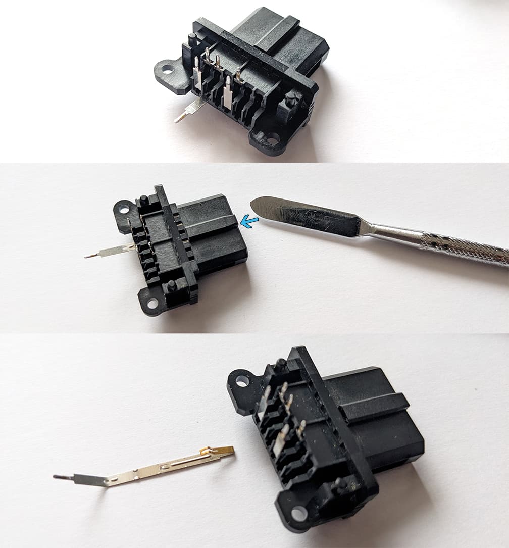
Open the NUS-003 RF box and desolder the AV connector. I found that simply running the soldering iron back and forth along the blue line indicated you should be able to separate the board from the AV connector pins:

Step 3
Next we need to remove these two pins and move them over to the open slots next to them.

Using your craft knife push in the ‘tabs’ on the two short and long pins we’re moving over:

Gently bend the long pin first to straighten it then using a spudger or other thin tool, push inside the AV port so the internal contact pin is pushed downwards so it can clear the rear hole as we pull on the straightened pin from behind (be careful not to put too much pressure on these pins as you pull) then do the same for the shorter pin:
Note: Make sure to restore the ‘tab’ on both long and short pins before inserting them into their new positions. The direction is different for both, the tab on the long pin points ‘downwards’ like in the picture below, the short points ‘upwards’:

Reinsert both pins into the open slot next to their original position, starting with the short and then the long, restoring their ‘L’ shape after each insert. The pins will now align to the pads ready for soldering:

Step 4
Next use your flat file to widen the existing rectangular hole so there is clearance for the audio port to fit. Keep testing to see if the shell closes as you file away material. When the shell closes you’ll next need to widen the hole for the S-Video cable to fit. I found 12mm is needed for cables with metal connectors, 11mm seemed okay for cables with plastic plugs. A clamp of sorts is highly recommended when you do your filing/grinding, the Stanley hobby vice is a good option if you’re looking to buy one. Remember to screw shut the shell for better rigidity when widening the hole.

Parts
4 pin mini-din with this particular footprint AliExpress:

Headphone Jack Socket PJ-325:

Note: PJ-392 style jacks like below will also work, you’ll have to wire up to the pads separately

PAL specific parts:
| Value | Type | Size | Quantity |
|---|---|---|---|
| 68nf | Ceramic capacitor | 1206 | 1 |
| 220uf | Tantalum capacitor | 6032 | 1 |
| 75 ohm | Resistor | 0805 | 2 |
PCB Gerbers:
NTSC Gerber file
PAL Gerber file
Note: You might be asked if you want Plated holes or Non-plated holes for the area of the PCB where the AV port solders onto by your choice of manufacturer, you want Non-plated.
Bonus: NTSC version works on NTSC GameCubes


