I just read that there was a new, official NES Tetris released in 2018! On a Retro-Bit handheld NES clone.
Looks great.
Official?
Yes, licensed by The Tetris Company / Tetris Holding, so the game can legally use the Tetris name and logo.
press release
Wild stuff. Those monochromatic backgrounds creep me out for some reason though 
That’s straight out of Tengen (Atari) Tetris, 1988.
I never played the NES Tetris releases. Not feeling it 
Heathen! ![]()
I’ve been reading about NESmaker, a game maker type software app that outputs NES roms playable on real hardware or emulators. I want to make something.
NESticle source code released.
https://twitter.com/forestillusion/status/1108489892680470528?s=21
Ha, I need to try that.
I started on a couple of rom hacks a few years ago.
Started on my NESRGB project last night. First attempt at desoldering a through-hole IC like this, and it went pretty well. I was working with a nice quality Hakko iron, and a decent hand-solder sucker. I really struggled with 3 of the pins, but I don’t think I caused any damage to the board despite my best efforts.
After it was out, I was tracing the pins along the board and making sure I still had continuity to the correct places, and noticed that the three pins I struggled with all had continuity with each other. My heart sank and I was sure I had messed something up.
I then pulled up the schematics for the board:

Pins 15, 16, and 17 on the PPU were my problematic ones, and it turns out all three go to ground. I checked them out to the ground plane on the board, and they all ground just fine! WHEW.
With that out of the way, I was confident I could move forward. Time to solder the header into the NES board, & the header strips and PPU into the NESRGB. Everything went really smooth from here, and the soldering is all complete.


Looking good so far! Getting those pins out is the hardest part of the whole mod if you ask me. Going to do a full recap?
Did some more work tonight. Got all the wires attached to the NESRGB, and the wiring done for the RGB and S-video ports. Everything went really well, no struggles.


Component video board and audio jack is done. There’s a surprising amount of wiring here, I hope I can keep it all correct.

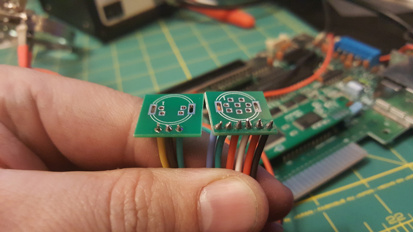
I hadn’t seen the component board before. Do you use an 8pin mini din to Component cable for the video out?
Nope, the little black jack there in the photo is what’s wired into the component video board. It’s a 3.5mm female jack. You then use a 3-way 3.5mm jack to component cable. You can see it here in this photo:

Ah, cool! I wired mine up to use an SNES multi-out.
Yeah that’s a really nice way of doing it too.
Almost done, just have to put the holes in the NES casing for the ports. It all tests out beautifully, and it looks amazing.


Nice job man!
Thanks. I’m a little surprised it worked first go, to be honest…
When I first fired it up it didn’t work, but it turned out to be the 3.5mm jack that’s used for the component video. It’s got a bad connection, and you have to wiggle it in the right way to get it to show the picture. I’ll have to email Tim Worthington for a replacement.